Dan Becker's Model Trains - Z Scale Subterrain

Laying Z scale track
As mentioned in the Z scale Prototype article, I made some tests with a model train track prototype, I designed a layout plan, and I was infected with enthusiasm for building another train layout.

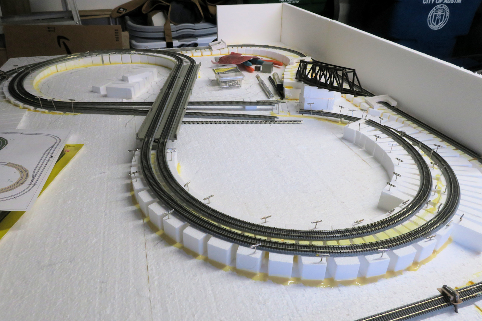
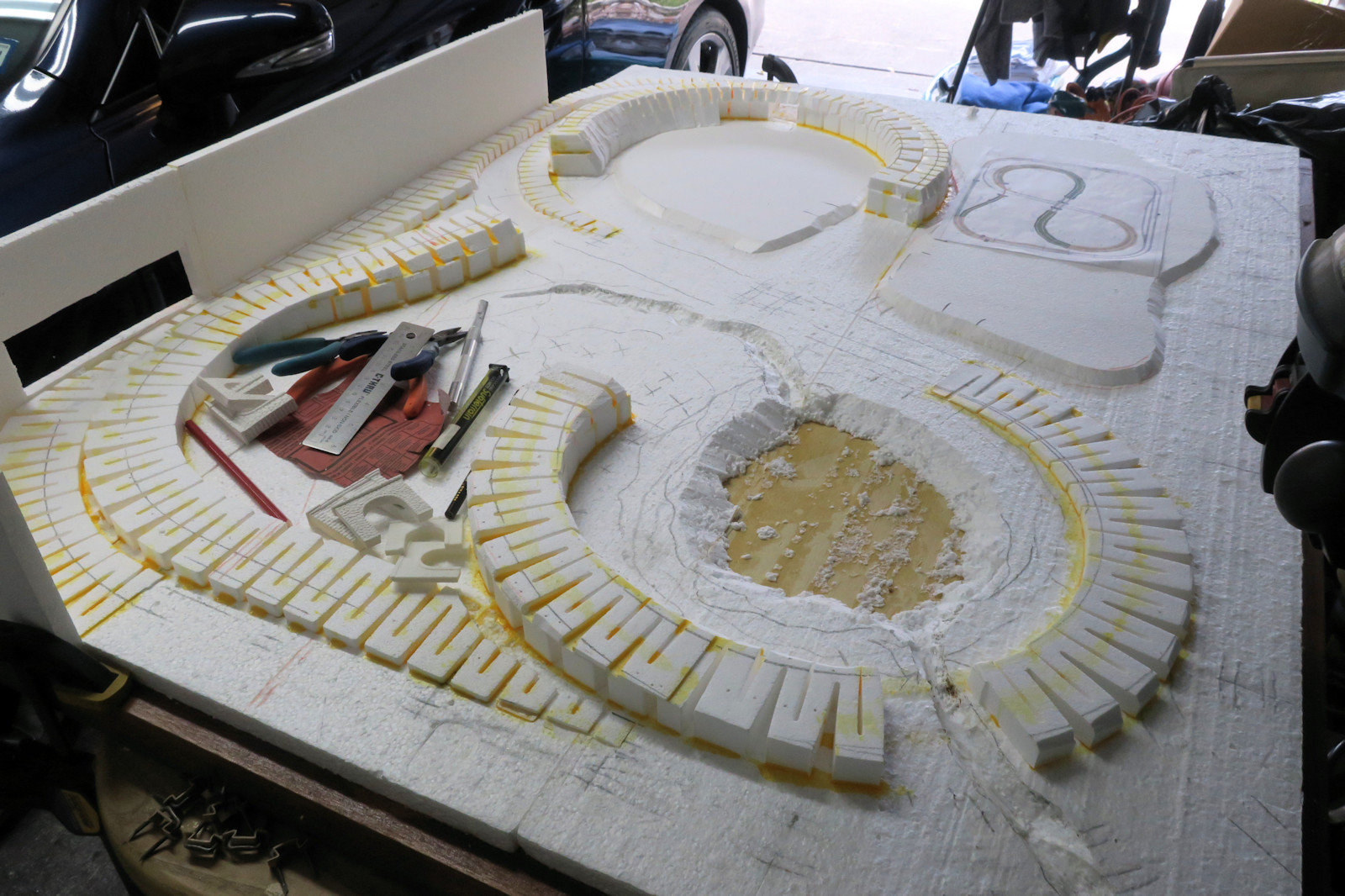
This article shows how to make a three dimensional surface under the train layout. Because these ramps and elevations, hills and valleys are beneath the bed of the track, they are also known as the subterrain.

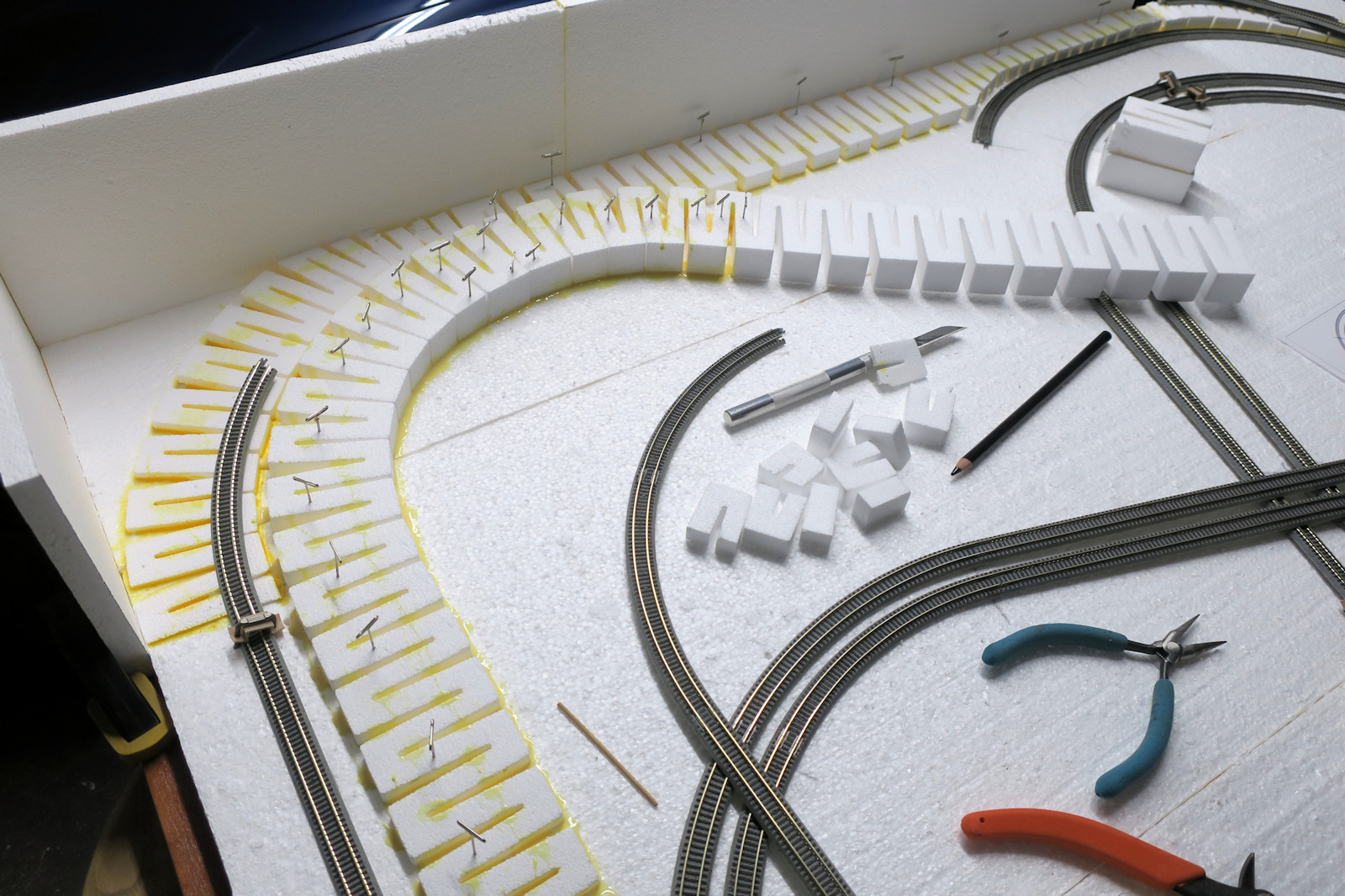
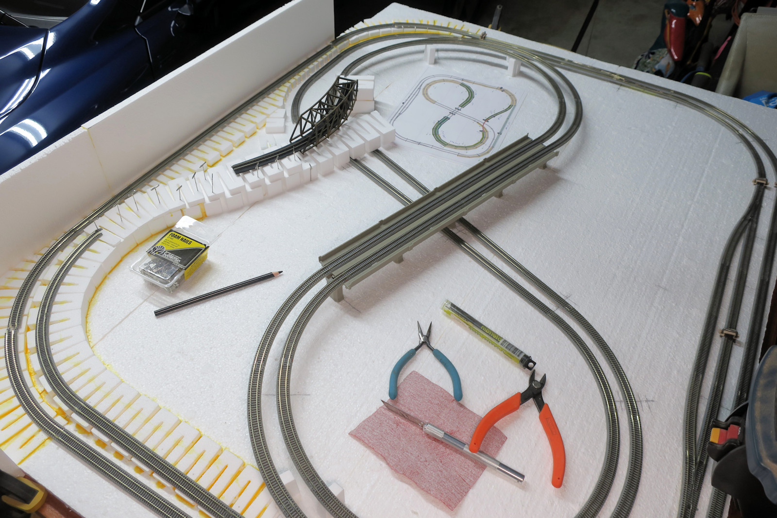
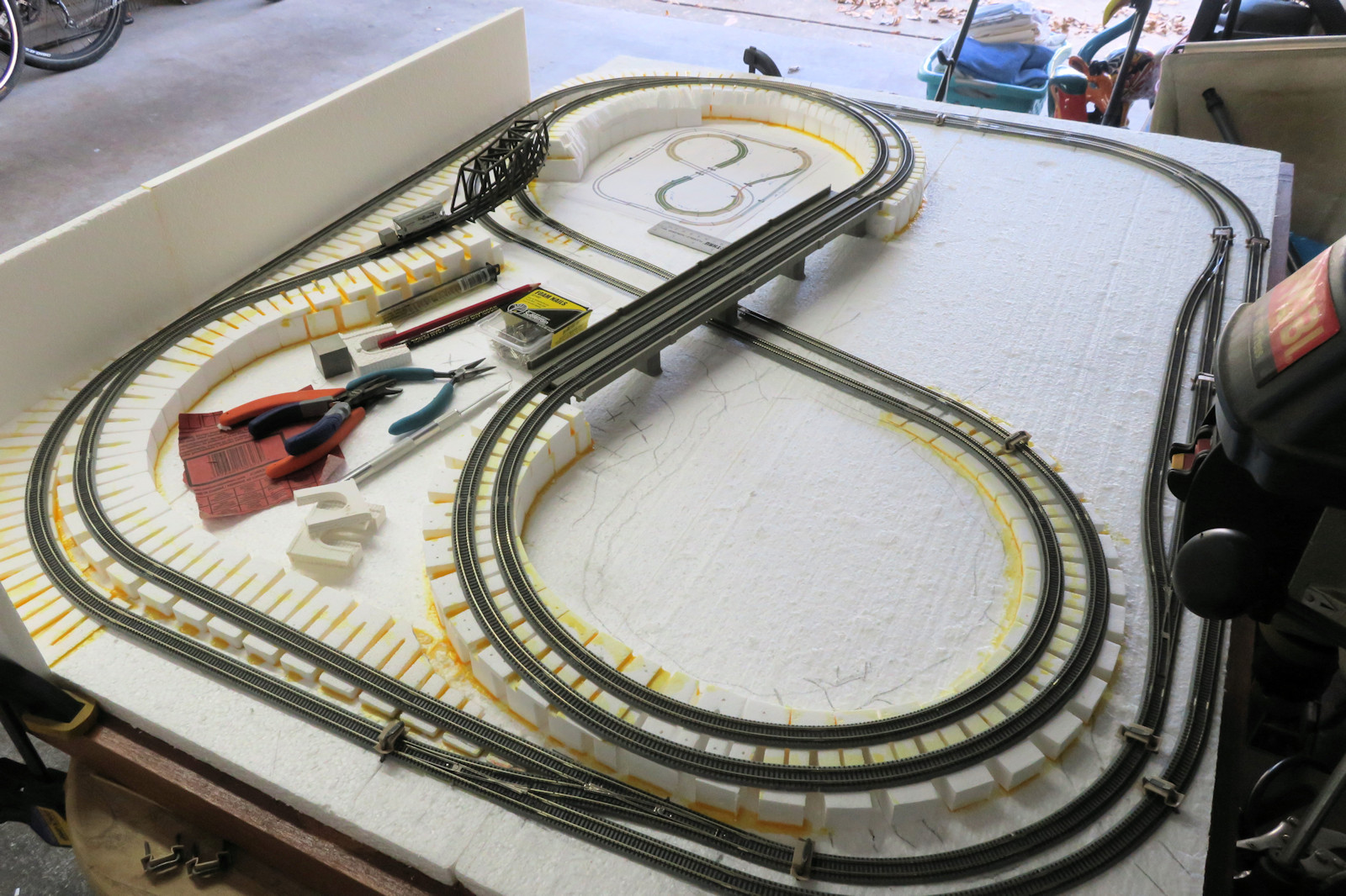
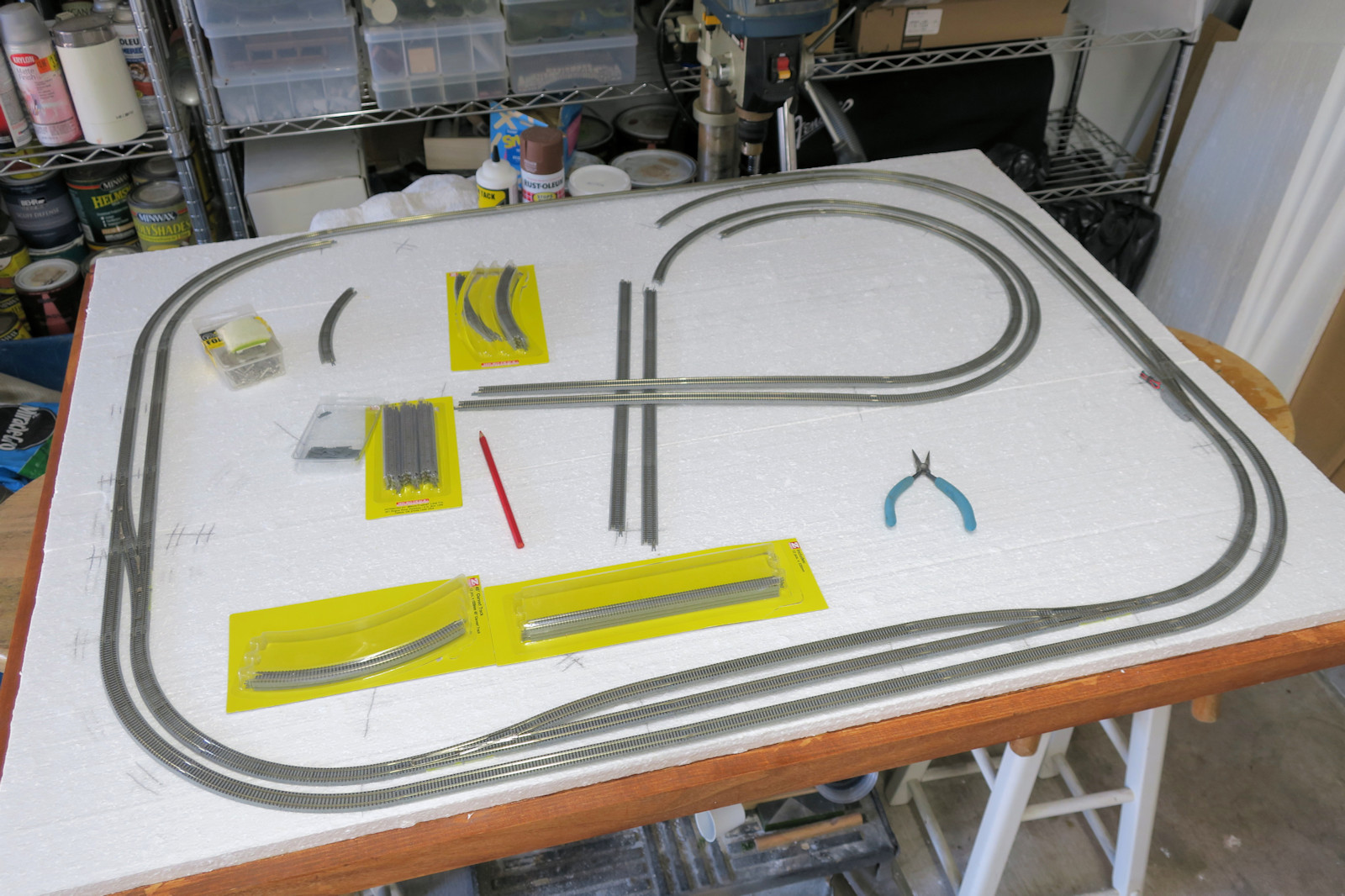
First we have to test that our layout in software can be realized in real world track pieces. This photo shows some of the Micro Trains Line track being layed out on the table. Sometimes a bit of stretching and compressing is needed to make all the curve fit, but things are looking smooth at this point

Gluing some ramps and risers

I think the best looking train layouts have lots of elevation changes. Here I show using styrofoam subterrain from Woodland Scenics to make the train track rise up from the train table.

Styrofoam is technically a Dow Chemical trademark for their extruded polystyrene foam (XPS). This white foam, also used in coffee cups and food containers, is actually expanded polystrene-bead foam (EPS). However, like kleenex or thermos, sometimes brand names become colloquial, and I will use the word styrofoam here.

The inclines are called ramps. The level elevations are called risers. Notice how the ramps and risers have a zig-zag pattern that allows you to form the curves of your layout. Very ingenious design!

Hat pins are used to form and hold the styrofoam pieces. Most any non-solvent glue can be used to fx the pieces in place. I am using Titebond II Premium Wood Glue which has a very good tacky grab, is water resistant, and very strong. It also has a yellow color which is easy to discern from the white foam. Much better than craft store white glues. However, TiteBond's curing time is about 12 hours, so don't use this if you are in a hurry.

A Rokuhan dual lane viaduct bridge

This photo shows the second bridge in my layout, a Rokuhan concrete viaduct bridge.

Concrete pier viaduct bridges were not very common in the United States 50 years ago. You see them more in modern train and highway bridges of the past 30 years. I like how this bridge can let roads and rivers flow underneath very easily.

The Rokuhan viaduct bridge is a nice modular design. You can vary the length, vary the pier heights, make it single or double track, and they even have curves.

Note that at this point much of the track is supported by temporary blocks.

More curving ramps and risers

Here we install more ramps and curves.

My original design for this layout had 2% grades which would be a one half inch rise over a four foot run of track. A four foot run is rather long in this layout, especially since I want a 1.5 inch clearance for all tunnels and bridges. So I opted for 4% grades which have a one inch rise over a four foot run. Some people on social media think 4% is a pretty tough load on the small Z scale locomotives, so they recommended running long trains with dual engines. We shall see.

The Woodland Scenics ramps and risers are scaled more towards N and HO scale trains. They are wide enough for double track in Z scale, but I am going to have do a lot of hacking and cutting in certain areas of the layout.

A tricky turn with an incline and a decline

This is a tricky part of the layout. From the concrete viaduct bridge at the top of the photo, the inner loop must incline to meet the higher black trestle bridge at the upper right. The outer loop must decline to go under the same bridge. The two single tracks must diverge in elevation.

A lot of cutting will be needed to diverge the two single tracks and make one side go up and the other side go down.

Finding the correct height of the truss bridge

This photo shows the clearance of trains coming down the hill and under the black truss bridge. I originally wanted the truss bridge to be 2 inches off the table, but that lead to some steep inclines on tight curves. Here I show that 1 3/4 inches is still enough clearance so the inclines are easier than the original design.

All the subterrain glued and cut

This photo shows an overview of the Z scale layout with all ramps and risers glued and in place.

The area with the tools on the left will be a mountainous area, extending over the tracks to the wall. The foreground loop will be a lake. The background loop on the left will be a factory area. And remaining area on the upper right will be a city area.

Running the first locomotive

And now we are ready for a test run on this layout! Here we have a General Motors EMD GP9 locomotive making its way over the highest part of the layout. The GP9 is in blue Missouri Pacific livery, which is common for Texas.

The locomotive found a few bumps and misaligned rails, but problem areas were fixed and now everything runs smoothly.

Here is a 38.8 MB MP4 video of the train run. Enjoy it.

Removing track for the next step

For the last photo of this chapter, we must remove all track and continue with the scenery.

In the vertical wall at left, I have cut a rectanglar access port to rescue any trains that might derail or tip over in the tunnels. This will be covered by a friction or magneticly held door.

I elevated the factory and city areas in the background. I also gouged out the basin for the lake down to the wooden table top below. With a knife I cut some ravines for creeks to flow in and out of the lake.

Two portals have been cut in the near and far ramps. This will allow road traffic to enter and exit the region.

Thanks for reading my articles. More train layout photos and articles will be posted in the near future.

Other articles in the scale train series include: