Dan Becker's Model Trains - Z Scale Curved Truss Bridge

Beautiful horizontal curved truss bridge
As mentioned in the Z scale Prototype article, I made some tests with a model train track prototype, I designed a layout plan, and I was infected with enthusiasm for building another train layout.

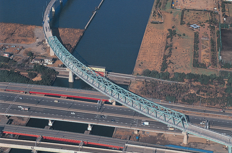
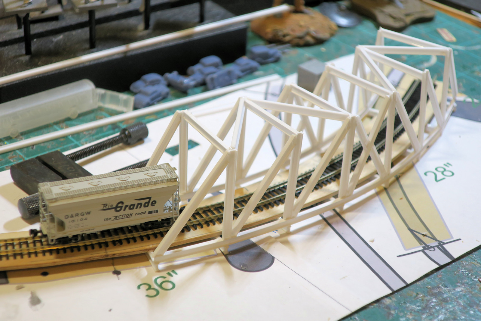
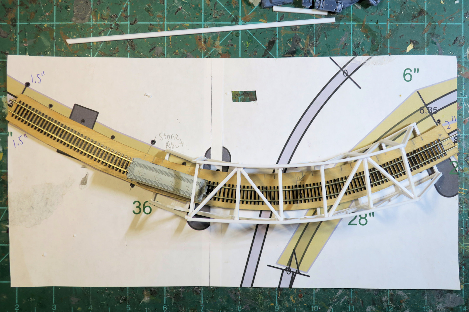
One of the interesting features of my Z scale layout is a horizontally curved track which flies over two of the tracks below. I thought this would be the visual highlight of my layout, so I went to the internet to find examples.

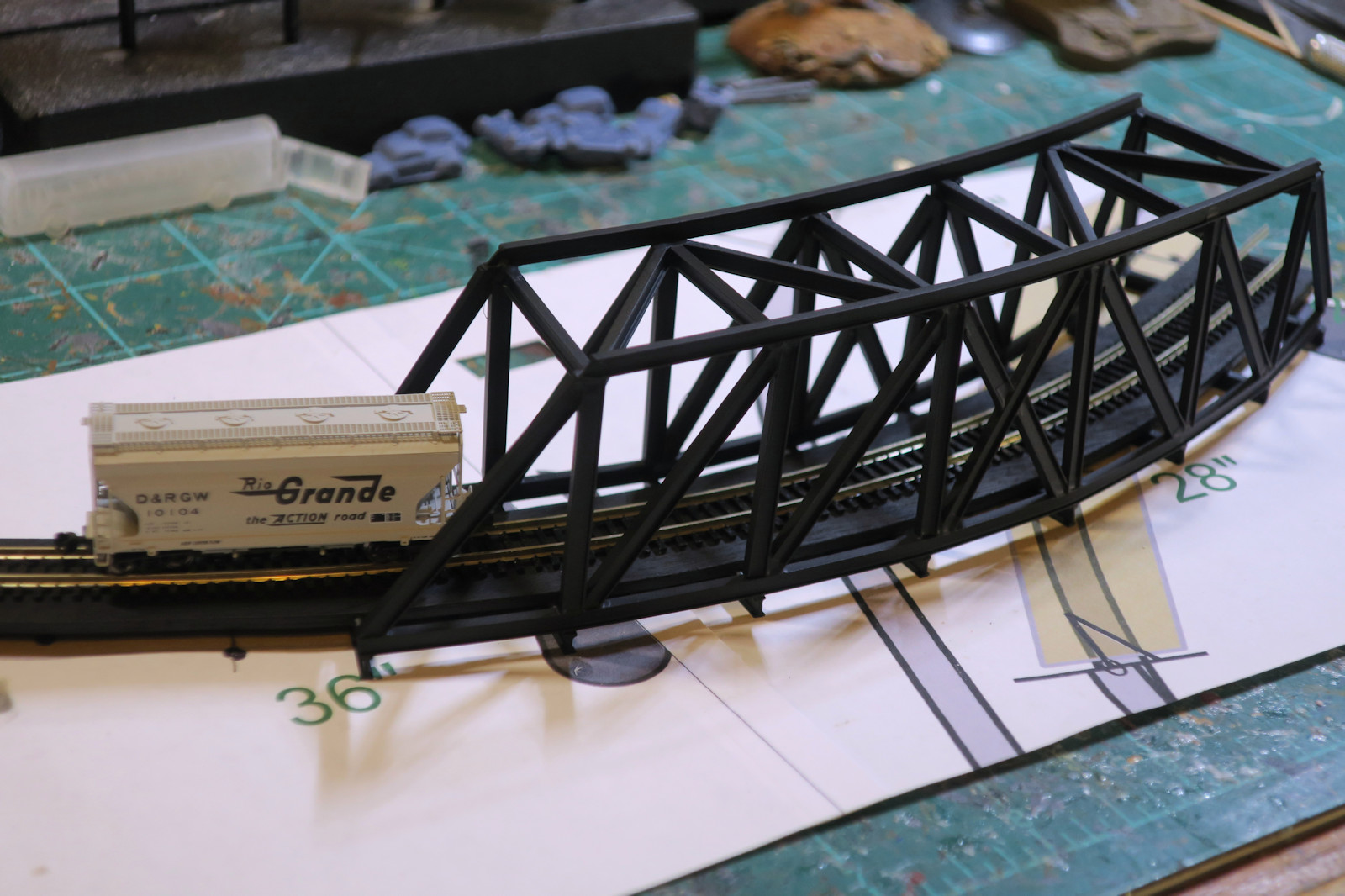
Of all the bridges I found, the one I thought most beautiful for my purpose is the Keiyo Line Yumenoshima Railway Bridge on the Yokogawa Bridge Corp. page. YBC is in Funabashicity, Chiba, Japan. This bridge is a continuous curve through-truss bridge.

There are no prebuilt Z scale train bridges that would have the same curve as mine. So, this is a bridge I am going to build from scratch using scale materials.

Figuring the train car clearance

The first thing I did figure out the height of the bridge. The bottom roadway of a truss bridge is known as a deck. I need to measure from the deck to the top of a typical car. This measurement also includes the track bed, the ties, and the rails.

As you can see from the photo, the top of this boxcar comes in at one inch (25.4mm) from the deck. I need to give some clearance for bigger cars, so I will make the top beams of my bridge 150% to 200% of this measurement.

A template for the bridge

Next I made a template for the bridge. Luckily the AnyRail software that I used to make the layout can print pages at 100% scale. For this bridge template I only needs two pages out of the entire 20 page layout.

On top of the template is a piece of Z scale flex track that I formed to follow the custom curve of the bridge. The reason I used flex track is that the AnyRail software can form curves that fit to the adjacent track pieces. The curve is done with splines which you can shape with control points, or the software can give you the most gradual curve that fits. This custom curve does not appear in the Micro Trains Line track product list, so flex track does the work.

Next I cut the deck of the bridge from basswood plywood. The plywood is about 1/8 inch thick (about 2mm), and I punctured some holes in the template to transfer the curve to the wood.

Finally I flipped the deck over and glued some scale I-beams from Evergreen Sale Models to the bottom of the deck. The I-beams are 1/8th of an inch high (3.2mm) part number 274. These beams are polystyrene, so liquid model cement works well to hold the plastic together.

These deck supporting I-beams are known as floor beams. If you would like to learn more about truss bridges, here is an excellent Wikipedia Truss Bridge article. This diagram sums up many of the parts of a truss bridge.

Curving the lower trusses

Once all the floor beams were in place on the bottom of the deck, I glued in the bottom curving truss I-beams. I used some heavy weights to hold the beams in place until the glue dried.

The plastic I-beams are flexible, but their natural tendency is to stay straight. This curve put the floor beams in tension, but the plastic floor beams handle this load very well.

A template for the vertical trusses

Once I have the curving bottom truss beams in place, the next step is to make the vertical truss supports. I made a template in Paint Shop Pro. Although the supports are the same height, the inside curve vertical beams and their diagonals are slightly narrower than those on the outside curve.

Testing the clearance

If you look at my real world prototype photo, you will see there are only diagonal braces supporting the top curving truss beams. My bridge has vertical support beand and braces that slope upward toward the center of the bridge. This is called a Howe Truss bridge. If the diagonals slope downward toward the center of the bridge, that is called a Pratt Truss.

Now the horizontal struts go into place along the top of the truss. As you see the test hopper car has plenty of head room before hitting the top struts.

The curved struts want to straighten

The last construction step is to glue the curving top truss beams in place. I did this one junction at a time: clamp the I-beam, glue it, let it dry, bend to the next joint, repeat.

When I got to the last joint, I realized that the elasticity of the I-beams wanted to straighten out the curved box. You can see that the right side of the truss looks a bit twisted out of the vertical planes. I should have nicked a few cuts in the I-beams to help it form the curve. However, in the end, a little bit of manual twisting, helped put the bridge sides closer to vertical.

The completed brige in black

Construction is done. I have painted my bridge in black primer. To make it more realistic, I will add a bit of rust wash, some dust, and some ballast on the ties. This unique bridge is now ready to run some trains.

Thanks for reading my articles. More train layout photos and articles will be posted in the near future.

Other articles in the scale train series include: