 For people who like to hurl!
This page is divided into the following sections:
This page discusses the design, construction, and firing of a 1/6 scale trebuchet. A trebuchet is a gravity powered catapult which was used extensively in the middle ages. They were so successful at knocking down stone walls that castle designers thickened the walls in an attempt to deal with these deadly siege machines.
Other types of siege weapons include:
At its most basic understanding, a trebuchet is simply a lever that uses centrifugal force to its advantage. Consider a playground seesaw. If a person is sitting on one end of a seesaw, and two people suddenly jump on the other end, the seated person is likely to go flying. Like a seesaw, a trebuchet is also pivoted in the middle, but the two participants are the counter-weight and the projectile. The counter-weight is usually much heavier than the projectile, typically by a ratio of 10 to 1 or more.
In addition to unequal weights, the trebuchet uses leverage. The counter-weight arm of the seesaw is usually shorter than the projectile arm by a ratio of 4 to 1 or more. This allows the longer projectile arm to move 4 times as far for each move of the shorter counter-weight arm.
The trebuchet also uses centrifugal force to launch the projectile. If you take a bucket of water and rapidly rotate it with your arm, water will stay in the bucket even when the bucket is upside down because the rotational acceleration holds the water in place. If you release the bucket, the circular acceleration of the bucket is converted to linear motion, and the bucket is launched in the air. Similarly, when you throw a ball, you rotate your forearm and wrist about your elbow, and releasing the ball causes it to launch linearly.
The trebuchet works the same way. The projectile slides backwards along a track. Then the arm pulls the sling skyward, causing the projectile to follow an arc. At the apex, one end of the sling releases the projectile, causing it to launch skyward. A key feature of the sling is that one end is fixed and one end releases. A small finger or prong holds the non-fixed end of the sling. When the sling is nearly vertical, the end of the sling slides of the prong and releases the projectile.
Finally, you may notice that the counter-weight arm is also hinged. Basically this allows the weight to fall more vertically than a non-hinged arm. The extra vertical travel allows gravity more time to pull on the weight and give the projectile some added acceleration.
This trebuchet is a 1/6 scale working model. Much of the mathematics and calculations of trebuchet design is discussed at The Algorithmic Beauty of the Trebuchet page. I used the Trebuchet Range Calculator to select the dimensions of my trebuchet.
Here are the dimensions:
| Height to pivot | 12 inches (30 cm) |
| Length of long arm | 15 inches (adjustable +/- 1 inch) (38 cm) |
| Length of short arm | 4 inches (adjustable +/- 0.5 inch) (10 cm) |
| Length of launch channel and sling | 12 inches (30 cm) |
| Length of counter-weight arm | 4 inches (10 cm) |
| Weight of counter weight | 5 pounds (2 kg) |
| Weight of typical projectile | 0.25 pounds (0.1 kg) |
| Range | About 33 feet (10 m) |
| Accuracy | + / - 1 foot or about 5% (0.3 m) |
The Trebuchet Range Calculator predicted a 0.25 pound projectile would fly 12 feet. I used a 0.1 pound projectile (a small rubber ball from a beach paddleball game) and achieved regular launches of 33 feet or more. The predictions are in line with what happened in the real world.
Following is an estimated Bill of Materials to construct one of these trebuchets. Please contact me if I've forgotten anything
| Item | Amount | Notes |
|---|---|---|
| 1/4" x 1/4" (6 mm) basswood stock | 3 24" (60 cm) lengths | frame |
| 3/8" x 3/8" (10 mm) basswood stock | 2 24" (60 cm) lengths | throwing arm |
| 1/4" x 1/2" (6 x 13) basswood stock | 2 24" lengths | projectile trough, vertical supports |
| 1/4" (6 mm) metal rod | about 6" (15 cm) | pivot axle, counter-weight hanger |
| counterweight | about 5 lb. (2 kg) | consider diver's weight, weightlifting discs, coffee can of nuts and bolts, fishing lure weights |
| leather or cloth | about 4 sq inches (26 sq cm) | projectile pouch |
| twine or cord | about 6 feet (2 m) | sling rope, launch rope |
| various hardware | - | hooks for launch pins, links for hanging counter-weight |
| wire clothes hanger | 1 | fasten trebuchet to earth or other fixed object |
| pebbles, rubber balls, eggs, jelly beans, peppermint candies, dog poo | 3 | projectiles |
The model is constructed with bass wood and materials found at any hobby shop. Bass wood is a soft wood similar to pine and slightly stronger and heavier than balsa wood. For added strength, you could also construct a trebuchet out of walnut or other hard wood, but the cutting and sanding would be a bit more difficult. Materials cost about $10 and the entire project required about 1 hour of design work and 8 hours of construction. Following is a pictorial guide to the construction.
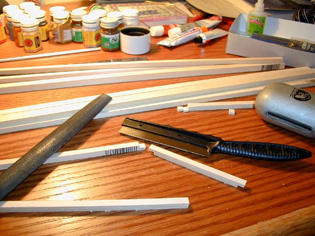 Here is my work bench.
Notice that I cut a few pieces down to size.
I typically use lap joints and Elmer's Carpenter's Wood Glue.
A lap joint is visible in the photo where the ends of the wood stock
are cut so they overlap each other when glued.
The lap joints are not really necessary, but they are so easy to
do in the soft wood, and it gives the trebuchet a nice touch.
The glue is much stronger than the wood and my trebuchet
has not failed after about 50 firings.
The wood weight of the model is about 5% of the counter-weight.
It is amazing how such little material is so strong.
Here is my work bench.
Notice that I cut a few pieces down to size.
I typically use lap joints and Elmer's Carpenter's Wood Glue.
A lap joint is visible in the photo where the ends of the wood stock
are cut so they overlap each other when glued.
The lap joints are not really necessary, but they are so easy to
do in the soft wood, and it gives the trebuchet a nice touch.
The glue is much stronger than the wood and my trebuchet
has not failed after about 50 firings.
The wood weight of the model is about 5% of the counter-weight.
It is amazing how such little material is so strong.
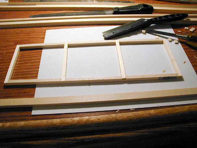 First, I constructed the base using 1/4" (6 mm) square bass wood.
The base is 12" by 4" (30 x 10 cm).
I later found that the trebuchet experiences quite a bit of
side to side rocking, and a wider base might be more appropriate.
Build side supporting projections if you like.
Another option is to do like I did and fix the base of the trebuchet
to the ground.
This can be done with weights or anchors.
I cut a few wire coat hangers to anchor the base to the lawn when launching.
First, I constructed the base using 1/4" (6 mm) square bass wood.
The base is 12" by 4" (30 x 10 cm).
I later found that the trebuchet experiences quite a bit of
side to side rocking, and a wider base might be more appropriate.
Build side supporting projections if you like.
Another option is to do like I did and fix the base of the trebuchet
to the ground.
This can be done with weights or anchors.
I cut a few wire coat hangers to anchor the base to the lawn when launching.
 This shows the construction of the vertical supporting arms
for the trebuchet.
I made the verticals 12" (30 cm) and lapped the bottom edge to the base.
The material is 1/4" by 1/2" (6 x 13 mm) bass wood.
Since these posts support the entire weight of the arm and the counter weight,
looking back I wish I would have used 1/2" by 1/2" (13 x 13 mm ) bass wood for a beefer
construction.
This would have made the pivot area thicker and more likely
to with stand the rotational forces of the arm.
This shows the construction of the vertical supporting arms
for the trebuchet.
I made the verticals 12" (30 cm) and lapped the bottom edge to the base.
The material is 1/4" by 1/2" (6 x 13 mm) bass wood.
Since these posts support the entire weight of the arm and the counter weight,
looking back I wish I would have used 1/2" by 1/2" (13 x 13 mm ) bass wood for a beefer
construction.
This would have made the pivot area thicker and more likely
to with stand the rotational forces of the arm.
Also shown is the pivot axle of the trebuchet arm.
Originally I used 3/16" (5 mm) aluminum tubing, but this bent under the weight of the
arm.
Here is shown 3/16" solid brass rod but you can use 1/4" (6mm).
Not only is it stronger, it also is more polished and has less friction
for the hurl.
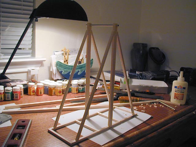 To help support the vertical post, I added diagonal braces of 1/4" by 1/4" (6 mm) bass wood.
I cut small wedges into both the vertical post and the base to anchor
these diagonal braces.
To help support the vertical post, I added diagonal braces of 1/4" by 1/4" (6 mm) bass wood.
I cut small wedges into both the vertical post and the base to anchor
these diagonal braces.
If you built a wider base, add some side supporting braces to prevent the supporting
braces from wobbling side to side.
Just remember to keep the center clear for the see-saw action of the trebuchet arm.
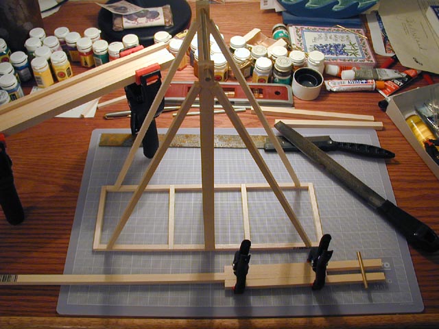 This image shows the assembly of the arm and the launch trough.
The arm is made of 3 pieces of 3/8" by 3/8" (10 mm) bass wood.
Twelve inches (30 cm) of the arm is extended alone and forms the longer end of the trebuchet arm.
Eight inches (20 cm) of the arm consists of two of these pieces which receive holes
for the pivot axle and the counter-weight arm axle.
Five inches (13 cm) of these 3 pieces overlap and provide a strong, triple strength
center section of the arm.
This image shows the assembly of the arm and the launch trough.
The arm is made of 3 pieces of 3/8" by 3/8" (10 mm) bass wood.
Twelve inches (30 cm) of the arm is extended alone and forms the longer end of the trebuchet arm.
Eight inches (20 cm) of the arm consists of two of these pieces which receive holes
for the pivot axle and the counter-weight arm axle.
Five inches (13 cm) of these 3 pieces overlap and provide a strong, triple strength
center section of the arm.
The launch trough guides the projectile as firing begins.
Here I glue four pieces of 1/4" by 1/2" wood together.
Two pieces form the base of the channel.
Once piece on each side forms the walls of the channel.
Later, this trough is glued to the base of the trebuchet.
 Here is a close-up of the arm and the pivot axle.
Notice that there are 5 holes for the axle in case you want to experiment
and get the best toss out of the trebuchet.
In practice I was happy with the center hole and used this for all launches.
Similarly I made 3 holes for the counter-weight arm, but I used the center
hole which is one inch from the end of the shorter arm.
The axle is a friction fit and nothing else holds it in place.
It extends about 1/2" (13 mm) beyond each vertical post arm and provides
much of the lateral stiffness of the trebuchet.
Here is a close-up of the arm and the pivot axle.
Notice that there are 5 holes for the axle in case you want to experiment
and get the best toss out of the trebuchet.
In practice I was happy with the center hole and used this for all launches.
Similarly I made 3 holes for the counter-weight arm, but I used the center
hole which is one inch from the end of the shorter arm.
The axle is a friction fit and nothing else holds it in place.
It extends about 1/2" (13 mm) beyond each vertical post arm and provides
much of the lateral stiffness of the trebuchet.
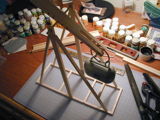 Here is a view of the counter-weight.
I used a 5 pound (2 kg) weight from scuba diver's dive belt.
It is vinyl plastic coated lead and is very dense for its size.
You can use any compact mass for the counterweight:
tin can filled with nuts and bolts,
fishing sinkers,
weight lifter's weights,
or a bag of sand. Be creative.
Here is a view of the counter-weight.
I used a 5 pound (2 kg) weight from scuba diver's dive belt.
It is vinyl plastic coated lead and is very dense for its size.
You can use any compact mass for the counterweight:
tin can filled with nuts and bolts,
fishing sinkers,
weight lifter's weights,
or a bag of sand. Be creative.
Two eyelets are screwed into the lead, and a large key ring
attaches the eyelets to the counter-weight axle.
The key ring is a split type that can unhinge to help detach the weight.
In practice, this large key ring was the only item that failed on the
trebuchet, often unhinging and dropping the weight.
However, because it and the axle are metal on metal,
there was very little friction in the rotation of the weight arm.
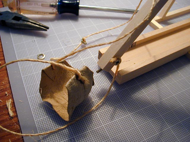 Here is a detail of the sling and the projectile pouch.
The sling is a pouch connected to two equal lengths of rope or string.
I trimmed an "eye-shaped" piece off a leather automobile chamois cloth
and glued the corners into a reinforced triangular fold.
Then I tied some ordinary twine, about 8 inches (20 cm) to the pouch
and froze the knots in place with some glue.
One end of the sling is fixed to end of the throwing arm.
Here I knotted the fixed end to a screw near the end of the throwing.
Here is a detail of the sling and the projectile pouch.
The sling is a pouch connected to two equal lengths of rope or string.
I trimmed an "eye-shaped" piece off a leather automobile chamois cloth
and glued the corners into a reinforced triangular fold.
Then I tied some ordinary twine, about 8 inches (20 cm) to the pouch
and froze the knots in place with some glue.
One end of the sling is fixed to end of the throwing arm.
Here I knotted the fixed end to a screw near the end of the throwing.
The other end of the sling rope is tied to a small washer which is placed over
a metal prong that sticks out from the end of the throwing arm.
The idea behind the hurl is that the two ends of the string attached to the
pouch are both pulled skyward when the trebuchet is fired.
As the throwing arm moves in a large circle, the two string, the closed pouch,
and the projectile are whipped around from a resting position on the ground into the air.
When the throwing arm is nearly vertical, one end of the sling is
released, allowing the pouch to open and the projectile to lauch forward.
Here, the washer slides off of the prong in the end of the throwing arm
and projectile flies free from the trebuchet.
 The prong sticks almost straight out of the end of the throwing arm.
It can be a small nail or screw, or some eyelet or hook that has been
clipped or straightened.
Initially you can have it point straight out of the throwing arm. However,
you will find this releases the sling too soon and the projectile goes
straight up. Thus, you bend it forward slightly (about 20 to 30 degrees)
in the direction that the arm is throwing. This holds the loose end of
the sling a little bit longer in the throw and makes the projectile go forward.
Experiment and bend your prong so the projectile release at a 45 degree
elevation from horizontal. This will get you the most distance.
The prong sticks almost straight out of the end of the throwing arm.
It can be a small nail or screw, or some eyelet or hook that has been
clipped or straightened.
Initially you can have it point straight out of the throwing arm. However,
you will find this releases the sling too soon and the projectile goes
straight up. Thus, you bend it forward slightly (about 20 to 30 degrees)
in the direction that the arm is throwing. This holds the loose end of
the sling a little bit longer in the throw and makes the projectile go forward.
Experiment and bend your prong so the projectile release at a 45 degree
elevation from horizontal. This will get you the most distance.
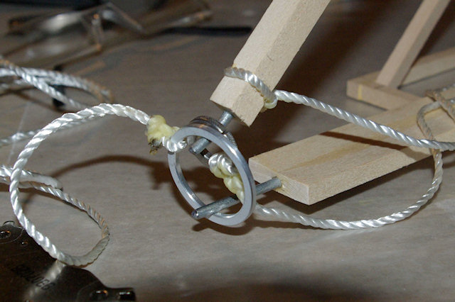
To the right is a photo of trebuchet trigger constructed by reader Bill Blohm. You can see one end of the pouch rope tied and glued to the throwing arm. The other end of the pouch rope is tied and glued to a washer. The washer of the pouch rope is placed over the prong of the throwing arm. Bill's trigger consists of a 4 foot rope tied and glued to a larger washer. The large trigger washer is placed over the fixed prong in the base of the trebuchet and the curved prong in the end of the throwing arm. When firing, use the long trigger rope to yank off the large washer and release the throwing arm. Notice how Bill has curved the prong in the throwing arm slightly forward to hold onto the pouch sling for a little while longer than just a straight prong. Thanks for the photos Bill! This shows the trigger mechanism very clearly and was a source of questions for many readers.
Not shown is the small rubber paddle ball used as a projectile.
It is about 0.1 pounds, 1" in diameter and bright yellow.
You can use all sorts of items for projectiles as long as they are
lighter than the counter weight.
Some other ideas include small pebbles, eggs, jelly beans, peppermints and hard candies,
plastic toys, and dog poo.
In medieval times they used not only rocks to batter down walls, but
dead animals and all sorts of rotten things to wage biological warfare
on the residents of the castle.
Experiment with projectiles and see which mass can be thrown the
farthest.
Now for the fun part - firing the thing!
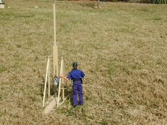
Here is our completed trebuchet and our brave launch manager Joe
showing the size and scale of the model.
Joe is 12" (30 cm) tall and nearly reaches the pivot axle.
Like all safety-conscious trebuchet firers, Joe is wearing Oakley safety glasses,
and he stands to the side of the machine.
He also carries a clipboard to log the result of the launches,
a two-way radio to communicate with the firing range manager,
and binoculars to see the impact of the projectile.
The throwing arm is cocked and ready to fire. The arm comes down from the pivot axle at an angle that reaches the end of the firing trough. The trigger pin holds onto the prong at the end of the arm which keeping the potential energy of the elevated counter-weight in place. The sling, pouch, and projectile are sitting in the firing trough at the base of the trebuchet. When the throwing arm fires, the projectile is dragged toward the back of the trebuchet along the trough. As the arm rotates skyward, the sling and the projectile dragged along, rotating in a graceful curve that begins at the back of the firing trough.
It is tough to see, but the trebuchet base is anchored to the lawn via 6 cut
coat hangers pressed into the ground.
The lawn looks like a typical mid-January lawn in Austin, Texas.
Conditions are bright and sunny, 65 degrees with little wind.
Aircraft have been warned that this launch range is a restricted air space.
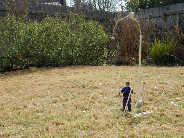
 Here we see the first test firing!
The arm is nearly vertical and travelling at high speed.
The counter-weight has reached the bottom of its travel.
Here we see the first test firing!
The arm is nearly vertical and travelling at high speed.
The counter-weight has reached the bottom of its travel.
Just visible in the top of the picture is the target, a crab apple tree
about 33 feet (10 m) from the trebuchet.
In practice, the trebuchet was highly accurate.
Each shot fell within a 1 foot (30 cm) radius at the base of the tree,
The shots were highly repeatable.
I did not have an adjustable counter-weight, but other
trebuchets typically use a bucket of rocks as a counter-weight.
More or less rocks can be added or removed to finely tune the range.
 Here is a front 3/4 view of the trebuchet firing.
Once again the arm is vertical and the sling can be seen in mid flight.
The free end is undone, and the projectile has left the pouch and is on its way
to the target.
Here is a front 3/4 view of the trebuchet firing.
Once again the arm is vertical and the sling can be seen in mid flight.
The free end is undone, and the projectile has left the pouch and is on its way
to the target.
 Here is the opposite side view of another launch.
Once again the sling is loose and the projectile is on its way in the air.
Just visible to the left is the trigger rope leading off camera to our lovely
trebuchet firing assistant.
Here is the opposite side view of another launch.
Once again the sling is loose and the projectile is on its way in the air.
Just visible to the left is the trigger rope leading off camera to our lovely
trebuchet firing assistant.
This trebuchet model was an enjoyable and surprising project. The design and construction were both challenging and interesting, and this small project allows you to exercise both your mind and your hands. It was surprising because the mathematical model corresponded so well with the range and actual performance in the field. For an object that is 12" tall and works on only gravity to fire an object 33 feet attests to the beauty and pragmatism of the trebuchet design. Second, the accuracy of the trebuchet was uncanny. Hitting a 1 foot radius circle repeatedly from a distance of 33 feet amounts to a less than 3% error. Not bad for a small model.
If you have read this far, thank you for showing interest in the project, and I hope you found this page enjoyable. Over the years I have received many hundreds of emails on the project, and I appreciate the feedback, suggestions, and questions. Keep them coming. It is wonderful to hear about all the family hobby time, the school science and physics projects, the dog tennis ball exercise machines, and the explorations and variations done by so many people.
Read more about trebuchets and ancient artillery at trebuchet.com. Coming next time, explosive and flammable projectiles.
People interested in ancient technology and society may also find these articles interesting: