Dan Becker's Current Limiter Project
 |
| Current limiter parts |
This article shows you how to make a current limiter circuit that helps protectan electrical project that you are powering up for the first time thatmight have a short circuit in the wiring.For example, you've just wired up a new guitar amplifier from scratch, and youare worried that you might not have hooked up the fuse or the main power supplycorrectly.Rather than burn up your expensive amplifier, this current limiter circuitwill kick in, protect your amplifier, and light up signifying a wiring problem.This particular project was made for North American wiring, with 120 volt alternatingcurrent power circuits.Other countries have other power values (e.g. the U.K has 240 V and 50 Hz AC), but theprinciples are the same.
This project is made with less than five dollars in parts.You will need a wirable extension cord,a light bulb socket,and about 20 cents of hookup wire.You will also need a solder iron, wire cutters, and a wire stripper.
 |
| Current limiter circuit diagram |
The idea behind this circuit is to use a light bulb in series with theoutlets you are trying to protect.We will wire one of the outlets on this extension cord in series with theothers.If the current draw on the protected outlets gets high, the lightbulb will light, indicating a high current draw.Additionally, light bulbs are current limiters.They will get to their maximum brightness and then the bulb filament resistancewill increase, limiting the circuit current.
By ohms law Power equals Current times Voltage.This is for DC circuits, but averages apply to AC circuits as well.A 40 W bulb across a 120 V AC supply will be limited to 40W/120V to about 0.33 amps.Similarly a 100 W bulb across a 120 V AC supply will be limited to 100W/120V to about 0.83 amps.As the bulb lights up, the filament resistance will increase, sothese figures are just ballpark figures.The actual current will be less.
 |
| Belkin extension cord |
In the United States, modern house wiring consists of 3 wires.A green wireconnects to ground or earth which is a circuit reference point, always at 0 volts.In addition to ground, the green wire is usually connected to chassis and switch boxes to always keepthe protective boxes at ground potential and protect people from getting a shock.If a live wire touches the box, there usually is a big spark, and a fuse orcircuit breaker trips to shut off the circuit.A black wire known as hot, provides the 120 volts to a circuit.A white wire known as neutral, is used as the return wire for a circuit.In the U.S., outlets have a semi-circular hole for the ground,a slightly wider spade hole for the neutral,and a slightly narrower spade hole for the hot connections.In fourth grade, the teacher asked me to run an errand, and gave methe keys to the artist supply closet.On the way back, I tested the power outlet by jamming the all-metalkeys into the hot and neutral holes of the hallway power outlet.I don't think they ever knew why the circuit breakers tripped on thatwing of the school, but the other students were happy that the lights went out.
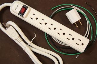
This Belkin extension cord makes an ideal starting point for our circuit.First of all, it is screwed not glue together, indicating that we can openit up and work on it.Second, it is cheap. It cost about $3.50 at Home Depot whichis interesting since the extension cord unwired part cost $9.00.It pays to shop.Finally, this extension cord has an on-off switch and a circuit breaker.So you don't have to plug it in and out for testing.And you also have an additional protective measure in case of a short circuit.
 |
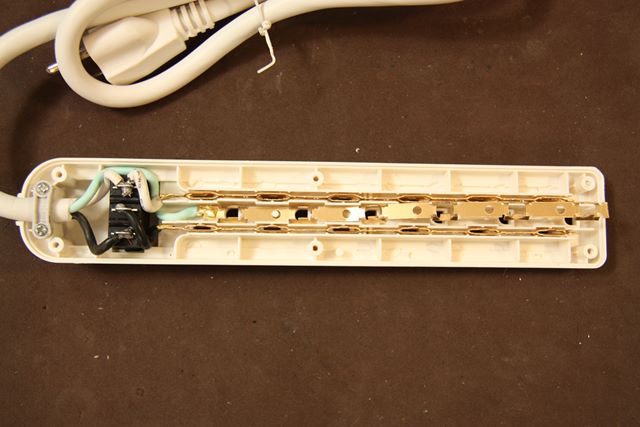
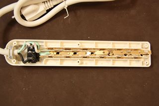
| Belkin extension cord close up |
Notice the economical beauty of this extension cord.A strain-relieved wire enters at the left.It goes through the circuit breaker.Then it attaches to 3 cheap, stamped brass busses for the 6 outlets.The busses show that all grounds are connected in parallel,all neutrals are connected in parallel,and all hots are connected in parallel.
 |
| Modifications |
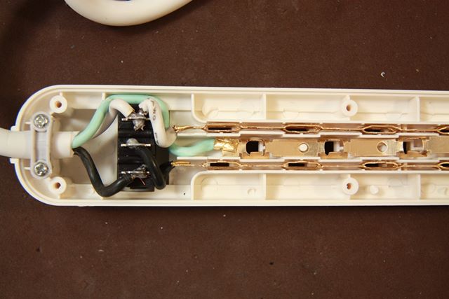
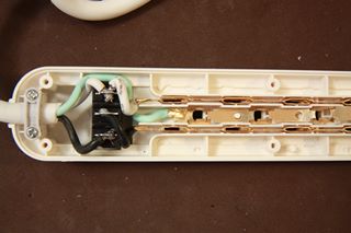
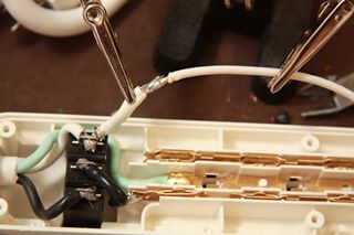
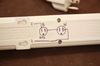
First cut the hot bus, separating the first outlet hot from the rest of the bus.Then, disconnect the white neutral wire from the neutral bus,and connect it to the disconnected hot bus of the remaining outlets.You might have to knock down some of the plastic ribs to feed the wire.Notice, that you do not have to change the green ground wire or the ground bus.
 |
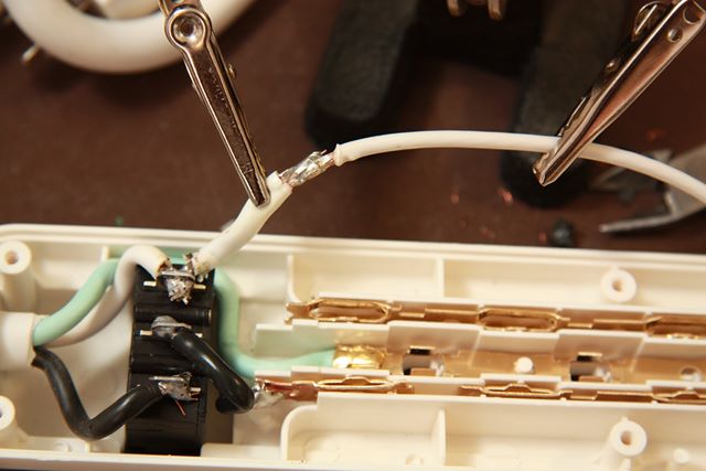
| Completed circuit |
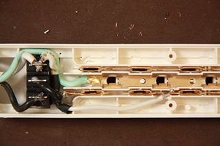
Here is the competed circuit.Trace the circuit in your mind.The current enters the extension cord through the black hot wire. It goes through the circuit breaker.Then it goes to the hot connection of the first outlet.The light bulb filament bridges the first outlet from hot to neutral.From neutral of the first outlet, the current can go through any of the the other neutralon the other outlets.It can go through any one of the other outlets,returning to the white neutral wire to complete the circuit.
 |
| Warnings |
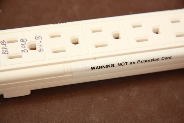
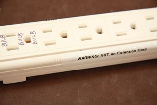
Mark the extension cord with some warnings.This contraption will not function without a bulb in place,so it should not do any harm to any family member who accidentallyuses it in place of an extension cord.However, in my family, things that don't work usually go immediately in the garbage or recycling bin.So you might want to mark and save your handy work.
 |
| Diagram |
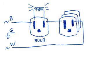
Additionally, I put a little circuit diagram on the bottom of the device.This helps when you fish this out of a drawer years later, and youwonder what this device is.
 |
| First test, open circuit |
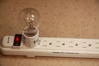
This photo shows the current limiter with a 40W bulb in place.The limiter is plugged into the wall and the switch is on,glowing red, showing power to the circuit.However, with no devices plugged in, this is an open circuit.Notice the bulb filament is not lit.(There are some room reflections on the bulb, but the filament does not glow.)
 |
| Second test, low current load |
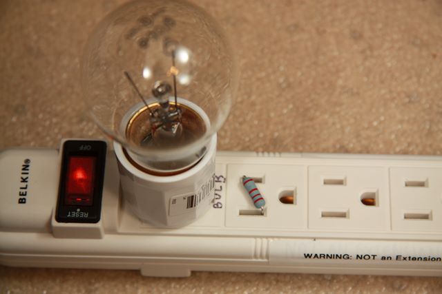
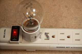
This photo shows the current limiter with a low current loadin place.A 2.2 kilo-ohm resistor in the second outlet completes the circuit.The current draw is about 0.05 amps, which is not enough to lightthe bulb,The bulb appears normal, and the 1 watt resistor passes the mild amount of currentwith no problems.
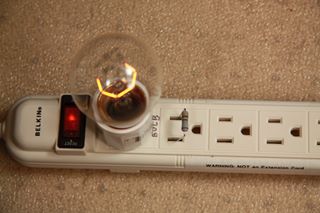 |
| Third test, high current load |
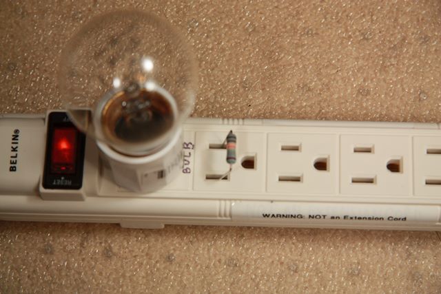
This photo shows the current limiter with a high current loadin place.A 470 ohm resistor in the second outlet completes the circuit.The current draw is about 0.25 amps, which is enough to lightthe bulb.This is a one watt resistor, but we are passing 0.25 amps through it.The power is 0.25 times the voltage drop which exceeds the power capability ofthe resistor.Warning. Do not run circuits like this for very long or they will fry.
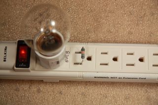 |
| Fourth test, destruction |
This photo shows the eventual demise of the circuit.Notice the resistor is glowing red hot and the light bulb has gone out.The resistor has burned out and it now an open circuit.The room is filled with the smell of burning carbon and plasticfrom the meltdown of the resistor.Unfortunately the bulb has not protected our circuit.That is because the bulb will run 0.33 amps, higher than this circuit can take.
It is hoped you have found an inexpensive and useful device for your electronic projects.This circuit can protect a guitar amplifier and provide an additionalmechanism of safety for you and your devices.Thanks for visiting the site and reading the article.More articles are found at the parentGuitars and Music page.