Dan Becker's Ardmore Tube Guitar Amplifier Build
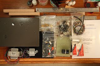 |
| The Ardmore Guitar Amplifier Kit Contents |
This article shows how I built a tube guitar amplifier from a kit.If you want to skip the build description and just hear the amplifier,just skip the article and jump to the sound clips.The kit is the 8 watt, 3 tube "Ardmore" kit sold by Guytronix based on a design from Gerhart Amps.There are many amp kits and amp designs out there.I chose this one because of the simplicity of the design,the attention to detail of the kit,and the good reviews and sound clips posted by many of the happy customers.This design has a two stage preamp based around a 12AX7 tube, andand a single ended output stage based around a pair of EL84 tubes.This amp design is similar to many early, low-power amps such as the Vox AC4.The photo shows the items included in the $375 kit.From left to right, there is a chassis, prepunched and drilled and readyfor mounting the components.It comes in basic black, but here I have painted it with Krylon "hammered bronze"spray paint which makes a shiny, hard, textured, gray finish.There are two Mercury Magnetics transformers, a large power trannie and asmaller output trannie.There are numerous bags of electronic components, hardware, jacks, pots,sockets and hookup wire.There are two decorative oak end caps which I ended up not using for my build.The circuit board is composite with metal turret pegs and the large power-supply-smoothing"death capacitor" mounted.There are some Sovtek brand tubes for bringing this monster to life.
Finally, one of the most important elements of any kit are the instructions.The instructions for this kit are generally very good with numerous illustrations,diagrams, and clear writing.
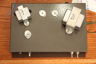 |
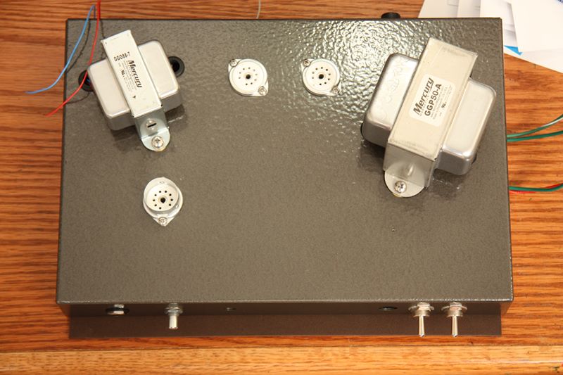
| Mounting transformers and sockets |
This kit is a simple amplifier that can be built byany hobbyist with decent soldering skills.If you are not comfortable with soldering, you should trya few other electronic projects before trying this one.You should also be skilled at cutting and stripping wires andhave knowledge of how to read a circuit diagram.Finally, you should be aware of the 400 volt "death cap",the big capacitor which can store lots of juice evenafter the plug as been pulled.If you drain this cap with a resistor or wire, you renderthe circuit safe for touching.This photo shows the transformers and tube sockets mounted on top ofthe chassis box.The box is 12" (30 cm) by 8" (20 cm) by 2" (5 cm) with wiring insideand bigger components on topThe odd angle of the transformers is to reduce inductive coupling and therefore noise and hum.I did not sense any inductive coupling, so I guess it works!Seriously though, with analog circuits, like cooking, many small details can add up to an improved final result.
Like many of the high-quality components in this kit, the sockets are heavy dutyceramic. No skimping or corner-cutting with this kit.
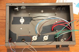 |
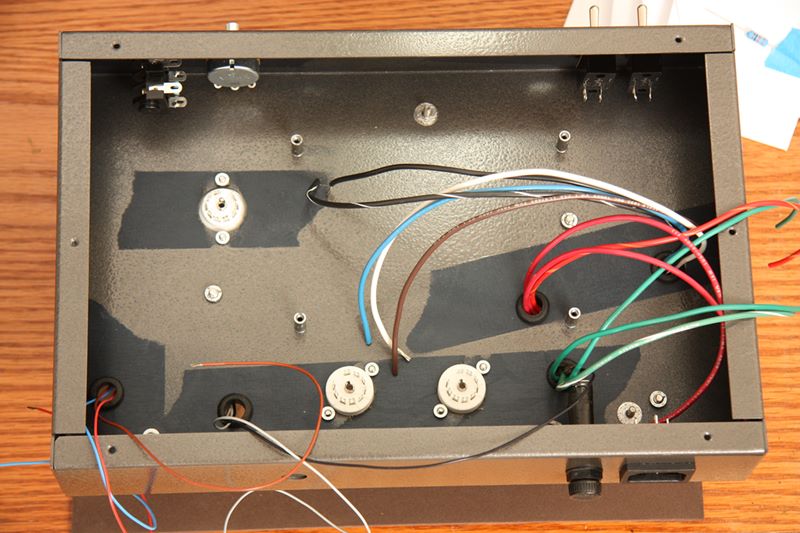
| Underside of chassis |
This photo shows the underside of the chassis with the tranniesand the tube sockets mounted.You can see some masking tape shadows where I prevented thetextured spray paint from clogging the mounting holes.At the top of this photo are the guitar jack, the volume control andthe power switches: one to turn on the power supply transformer,and the other to turn on the output transformer.At the bottom of photo will be the output speaker jack.I've added the fuse and main power jack.
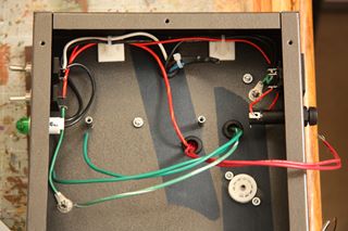 |
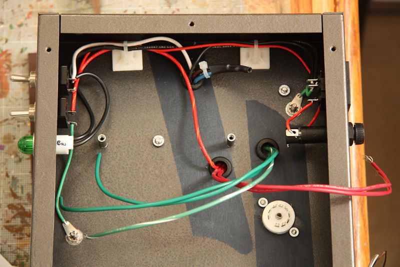
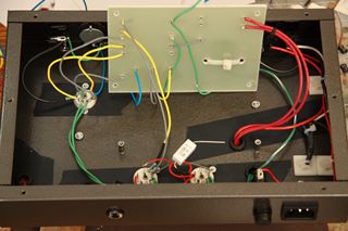
| Power hookup |
I diverged a bit from the instructions and worked on the hardware firstrather than the circuit board.This photo shows the hookup of the power section.Juice comes in from the AC power cord shown on the right here.It is protected by the fuse,and then routed to the on/off switches at the left.Once the on/off switches are thrown, the juice will berouted to the power supply transformerwhich has its beefy wires coming through the rubber-grommeted holesin the center.
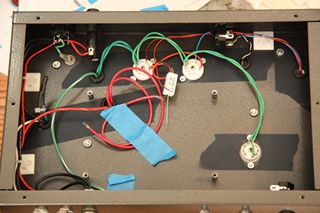 |
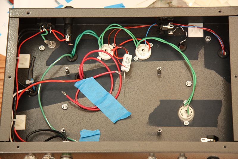
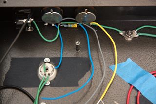
| Tube hookup |
This photo continues the power-hookup of the amplifier.The power transformer for this amplifier providesa 6.5 volt AC supply to heat up the tubes.You can see this pair of green wires gofrom the power trannie to each of the tube sockets.For the two EL84 tube sockets in the center, the green wires goto pins 4 and 5.(Pins are numbered 1 through 9, starting at the gapand going clockwise when viewed from the bottom here.)This photo shows my first mistake of the project.For the 12AX7 tube, one green wires should be hooked up to pin 9,and the other should be hooked up to both pins 4 and 5. The instructions and circuit diagrams show this.Inadvertently I have hooked one up to pin 4, andthe other to 5 and 9.This is a mistake that cost me debugging time later.More info to come on this topic.
 |
| Guitar input and tone |
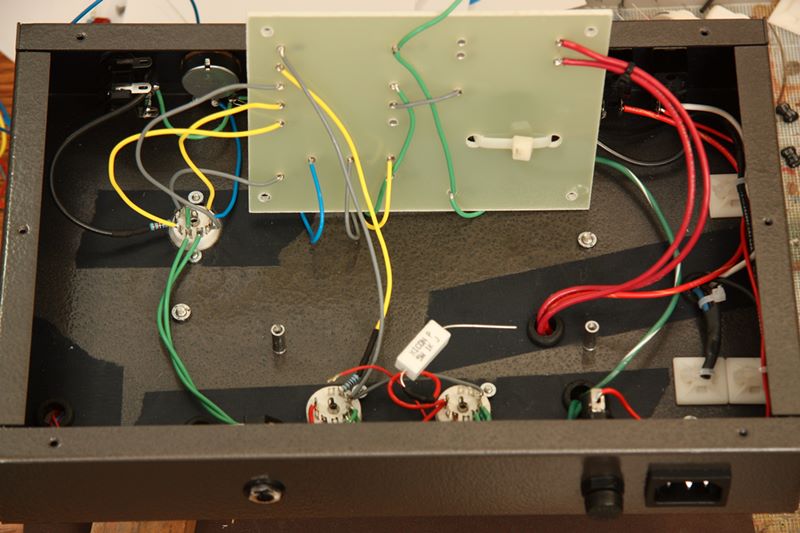
This photo shows the guitar input jack at the top left.The barely visible black shielded wire connects to thelugs of the jack and brings the signal to the preamp tube at the bottom right.Eventually this leadsback to the volume potentiometer at the top left.The volume pot sends the signal onto the tonecontrol at the top right.Like many simple tone controls, the potremoves high frequencies by usinga resistor/capacitor network to remove treble.I guess there is some wire color code convention used in amplifiers,but I have not really followed any scheme here.I generally use green for ground wires and red for power wires.The rest of the colors are up in the air.I use blue gray and yellow in various ways.
 |
| Circuit board hookup |
This photo shows the circuit board underside and preliminary connections.The signals from the preamp tube and the tone control attach to theunderside of the board on the left side here.The AC power supply enters via the heavy-duty read wires at right.Some green ground wires attach to the center of the underside.Finally, some output wires will go to the output sockets at the bottom.
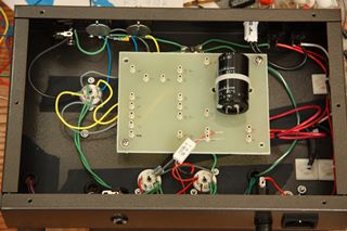 |
| Circuit board mounted |
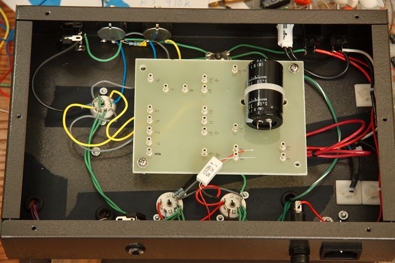
So the circuit board has been flipped into its final position andscrewed to the standoffs of the chassis box.I've left enough slack in the wires to enable the boardto flip up for debug purposes.
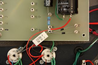 |
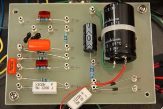
| Power circuit |
This photo shows a close-up of the power circuit that brings thisamplifier to life.The power transformer hooks up to turrets 18 and 19 on the right.Two rectifier diodes take the AC power signal and convertit to DC at turret 15. The big "death cap" helps to smooth out the power and make itnice and steady.Some of the power is diverted to the output tubes via thebig white 5 watt ceramic resistor in the center.You can see the signal on to pin 9 of both tubes.Some of the power is portioned out to the remaining circuitryto boost the tiny input signal.This is the essence of this whole circuit:getting the tiny guitar signal boosted and sent to the output speaker.
 |
| The hand wired circuit |
Up to this point, much of the kit build was highly mechanical.At this point, the electronic circuit hookup commences.It really is quite enjoyable to get to this stage and connect the electronics to the sturdy posts.This part goes very quickly, but has much of the visual impactof the guts of the guitar amplifiers.Most electrical engineers and electronic technicians can tell youthat resistors have a color code to describe their value.Some of those browns, blacks, grays, oranges, and golds are so similar, I recommend you DON'T attempt to read them.Most any digital volt meter can tell you the value of a resistor.So stop wasting time reading all those little bands, andjust let the meter do it for you.Your eyes will thank you.
 |
| Plug in tubes and give it life |
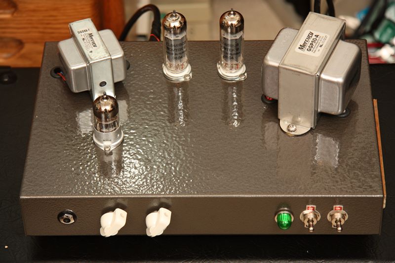
At this point, the guitar amplifier is assembledand ready to power up.Unfortunately, projects such as this still have a long way togo to completion.Debugging can be expected in any analog circuit, sodon't be disappointed that you don't hear the songs of thegods the moment you switch it on.If you have a variable AC power supply, also known as a variac,use that to bring up your amp.Slowly bring up the AC supply from zero to 120 volts.All the while, look for smoke, or fire, or tiny pops ofelectronic components committing suicide under stress.Luckily I did not have any calamities, but I still did nothear any sound from my amplifier.
A good kit supplier is invaluable.Rather than a large faceless corporation with a computerized help line,or some circuit guru with no time to mess with a beginner,Richard Guy of Guytronixis dedicated to customer support and helping his customers have thebest experience with their Guytronix amplfier kits.This man spent nearly 2 hours with me on phone debugging my mute guitar amplifier.
Together Richard and I probed and prodded the circuit searchingfor the problem.We measured the power supplies and saw the circuit boardwas getting power.We noted the output tubes were glowing nicely and their heaters weregetting 6.5 volts AC.We tickled the output tubes with a probe and heard clicks comingthrough the speakers.We measured the input jack to ensure that the guitar was connectedcorrectly.Finally we saw the mis-connection of the preamp tube.Richard waited patiently on the phone while I performed the correction.His sense of humor was evident as he instructed meto plug in my guitar, put all the volume controlsto maximum,and strike a giant full-volume E chord."All part of the testing process."
It sounded great with long sustain, low noise,nice ringing treble, and visceral low-end punch.
 |
| Amplifier cover |
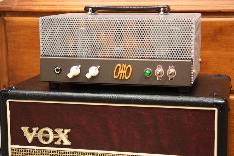
The amplifier was playable, but it was not quite done.I did not want to leave the tubes out in the open where I was sureto step on them or kick them.So I constructed a cover from perforated aluminum sheet,which still lets you view the lovely golden glow of the tubes as you play.This top was folded from a 12" by 24" piece of 0.063" aluminumwith 0.125" diameter holes at 0.1875" spacing which I boughtfrom Online Metalsfor $17 plus shipping.The metal cuts easily with tin snips and you can fold it over theedge of a table with hand pressure.A rubber Vox handle is bolted to the top and the normalbolts are used attach the cage to the chassis.I play the amp through another modded monstrosity.The speaker cabinet is an Epiphone that I bought off eBay,but it was missing the logo.So I found some ox blood colored vinyl leather and a logo andturned the cabinet into a faux-Vox.The speaker is an Eminence Red Coat "Governor" 8 ohm inside.
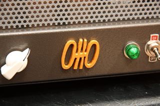 |
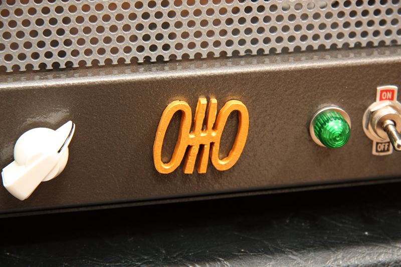
| Gold tone logo |
The amplifier looked kind of naked without some sort of logo,so I made my own.Don't go looking for an "Otto" amplifier at your localguitar shop.Only one exists at this point.The Otto logo was made from Super Sculpey modelling claythat was baked and hardened in an oven.Then I sanded it as best I could.I painted it with gold acrylic paint and glued it to the front.Who knows, maybe one day everyone will want an Otto.
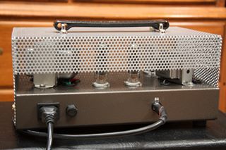 |
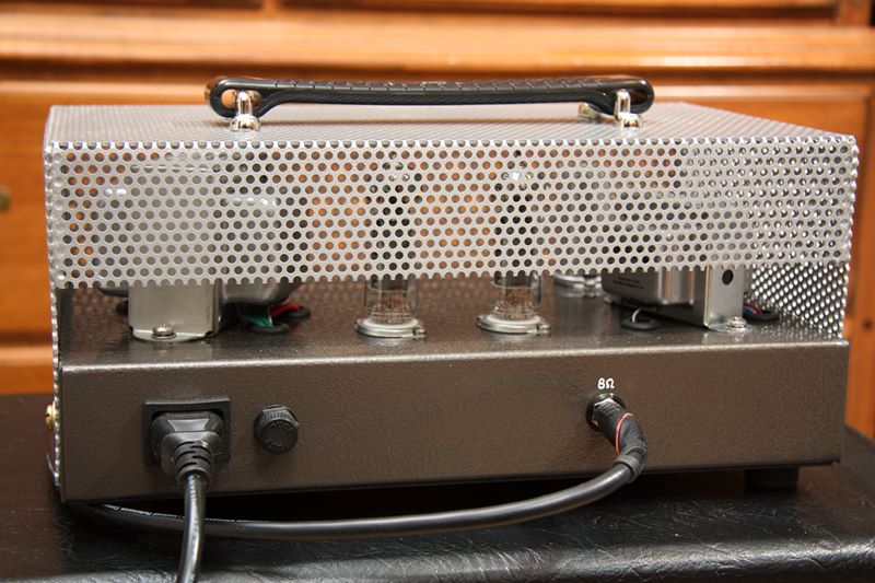
| Back of amp |
Here's the back of the amplifier.I left a one inch window into the interiorto give it a kind of "technician access" look to it.The output jack is hand painted with an 8 ohmlabel.
Sound Clips
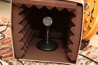 |
| Sound clips |
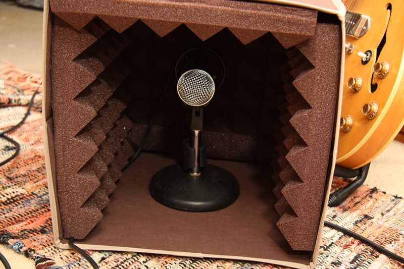
If you have been reading this far, I thank you, and hopefully I canreward you with some sound clips.Beware, I am a beginning guitarist, and did not spend a lot of timelearning and practicing these songs, but hopefully these soundgive you an idea of what is possible with this amplifier.The photo give you an idea of the recording process.I put my microphone into a folding Whitmor cube that is linedwith acoustic foam.The microphone goes into an Edirol UA-25EX to the USB port of the computer,and is recorded with open source Audacitysoftware.No processing is applied to the recording except to normalize the volume level.
- Clean neck - this is a simple E majorscale played on the neck pickup, clean, with low drive and low volume.Listen to the sustain on the final note.
- Clean bridge - this is a G minorscale played on the bridge pickup, clean, with low drive and low volume.
- I Can't Stand Up for Falling Down - this is the Homer Banks/Allen Jones song recorded by Elvis Costello in 1980played cleanly through both pickups.
- London Calling - this is the opening of London Calling by the Clash. The amplifier is being drivento give it that dirty dirty overdrive.
- Should I Stay or Should I Go? - this is the Clash song with a bit of overdrive and a Tech 21 reverb pedal in front.It sounds pretty roomy.
Thanks for visiting the site and reading the article.I hope you enjoyed the detailed photos and commentsand had fun listening to the sound clips.More articles are found at the parentGuitars and Music page.