 |
|
Warning. A tube amplifier contains some potentially lethal components.Do not attempt opening your amplifier unless you understand the risksand avoid any dangerous practices.Even after unplugging the amplifier, components can contained storedcharges that can give you a nasty shock.These changes are suitable for the intermediate electrical technician,a person with decent soldering skills, understanding of basic electricaltheory, and the ability to read circuit diagrams.
 |
The Vox AC15CC "custom classic" amplifier is a modern tube amplifier introduced by Vox in 2004 and discontinued in 2010.This amplifier attempted to reproduce the sounds of the original Vox AC series introducedin 1958, but using modern cost saving design and Chinese manufacturing.The sound of the amplifier is good, but can be improved with some upgradesand some modifications.
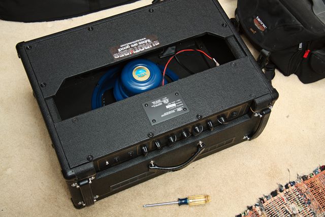
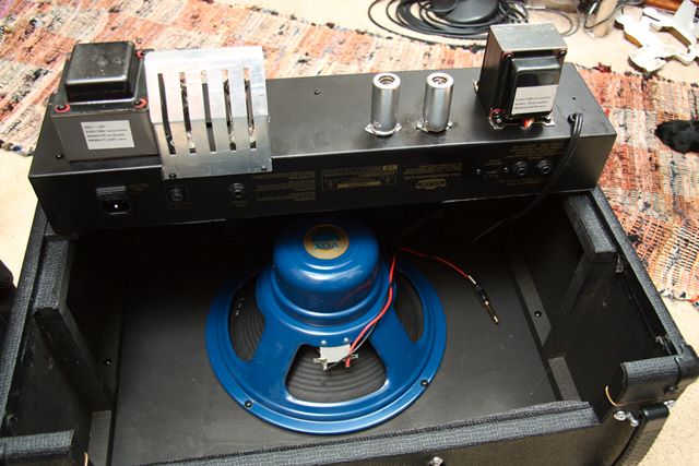
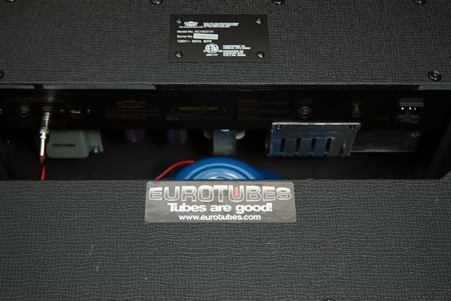
I purchased the AC15CC off eBay in 2009, and it sounded pretty good.If it sounded bad, I would not have invested more time in it.However, I added some new tubes and an Accutronics reverb tank, andthen it sounded really good.So I thought, why not try to make it even better and hence read up all I could on Vox AC15 mods.The Guitar Pug site had good explanations andMercury Magnetics had many Vox AC15-specific parts, so I decided to go for it.This photo shows the back of the Vox, its last moments on earth before being dissected by Dr. Frankenstein.
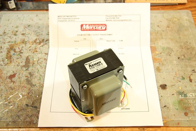 |
This photo shows the Mercury Magnetics VXO-15W-C replacement transformerspecifically designed for the Vox AC15CC series.It weighs about twice the weight of the original Sanecore transformer.It also comes with a nice spec sheet telling you thefunction of each of the output wires.
Many guitar amplifiers save money by putting in a tiny output transformer.This save material costs and shipping weight and freight costs.However, since the output transformer drives the speakers,skimping on this component can mean the speakers don't produce a nice tone.You can be assured the design calls for the smallest, cheapest workingcomponent, but not necessarily the best sounding.An analogy would be an automobile manufacturer putting in a 6 cylinder engineto save cost and weight, but the automobile can easily be upgraded to an 8 cylinder engine,and the 8 cylinder would provide better acceleration.
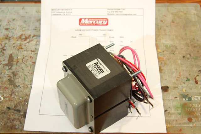 |
Here is the Mercury Magnetics power transformer VXP15-CC for the Vox AC1CC.This monster is also about twice the weight of the Vox-supplied Sanecore original transformer.It also comes with a nice spec sheet.
The power transformer provides the juice for the amplifier components.It does not really touch the guitar input signal or speaker output signal,but it provides supply voltage to most components.Any under-performance here means the component performance can sag andoutput could be affected.An analogy would be swapping out your automobile carburetor or fuel injectionsystem for a better one.It does not really increase the power output, but it ensures yourengine performs efficiently and generates all the power it can possibly do.
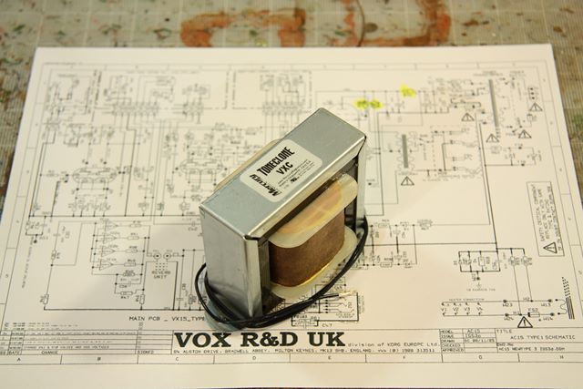 |
The last major upgrade I perform here is adding aMercury Magnetics VXC input choke.It only has two wires, so it does not really need a spec sheet.I did print off a circuit diagram herewhich has many of the modifications highlighted.
More on the choke later, but let me state the purpose of this modification.Many guitar amplifiers including the AC15CC have a "blocking resistor" thatthe input guitar signal passes through.The purpose of the resistor is to block AC input hum and noise that guitarmight pick up from the outside world and introduce to the amp.However this resistor blocks the guitar signal, both high frequency AC andlow frequency AC signal as well.The input resistor is cheap and easy to install on the manufacturingline, but does not do a very good job of reducing AC noise or leavingthe guitar signal alone.
A choke is a transformer with one winding. It has one wire wound around an iron core whichproduces a signal inductance and slows any ACsignal propagation.The choke can be designed to block the non-desirable portion of the incoming signaland leave more of the desirable portion.In short it does a better job than a resistor, and results inreduced hum, and better guitar bass response.
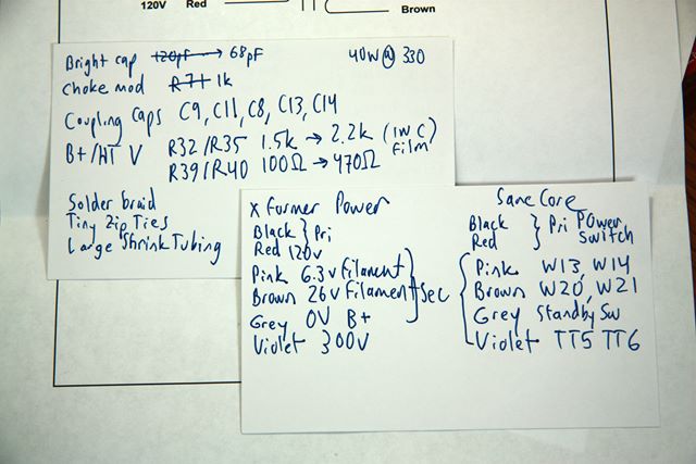 |
At this stage of the mods I peak into the guts without actually cutting or unsoldering anything.It's always best to plan your mods before doing any hacking.In addition to replacing the transformers andadding a choke,I also needed to replace a cracked guitar input jack.Another mod for Vox AC15s is to remove or reduce the bright capacitor.Here I make a big shopping list of all the components and supplies I need.I also write down the positions on the circuit diagram.Luckily, Vox has labeled the circuit board nicely, so it is easyto correlate the diagram to the board.
I also compare the new Mercury Magnetics transformer wires to the existingSancore. Luckily, the wires are the same, so this will be a drop inreplacement.Note all the wires and where they go to serve as a guide for your mods.Taking detailed photos can also help remind you where things should go.
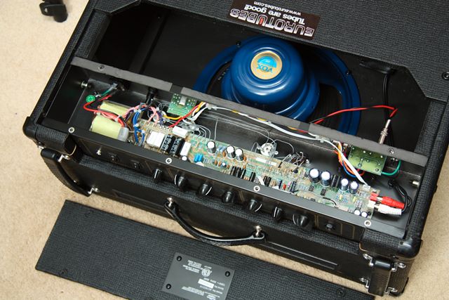 |
Here I remove the amplifier circuit board cover.You can see the guts are a mix of wires, connectors, and printed circuit boards.The amp speaker disconnects easily via a speaker jack, but the reverb tank RCA cables(at the far right of the board in this photo) aretoo big to snake out of the chassis. I disconnect these from the tank at thebottom of the case.
 |
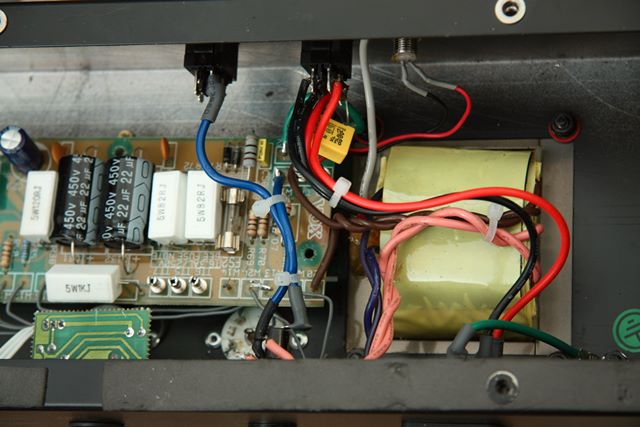
This photo shows the existing power supply transformer.It is the yellow wrapped square peeking through the chassis.You can see its connections to the power and standby switchesat the top.There is also connection to the input power at the bottom right (the mains),the fuse at the bottom, and the on/off light.Finally, several wires go to the main circuit boardto provide tube and board supply voltages and the heaterelements to the tubes (the 7 volt supply that causes the tubes to glow).
The two black can capacitors left of center are the "death caps".These high voltage caps smooth out the power supply voltage and keepthe tube input at a steady and deadly 400 to 450 volts.These are the caps that contain lots of energy and can give you anasty zap even after the amp has been unplugged.Proceed with caution in here.
 |
This photo shows the other side of the main circuit board.You can see connectors to the auxilliary boards at the top.Once connector goes to the guitar input jack board, at the extreme left of this photo.The other connectors go to the "pots board" which has the potentiometersthat amp control knobs twist to control the sound.
At the bottom are various wires that connect the printed circuitboard to the tube connectors.Note that one of them is brown plastic and the remainder are white ceramic.As I mentioned, this amp was purchased used off of eBay, and itappears the previous owner might have had some trouble with this last tube (V4, the last EL84 power tube).This important clue will factor into our story later.
 |
Here's a view of the guitar input jack board and the pots board.I need to replace this cracked guitar input jack, soI undo the nut and remove the guitar jack board.
 |
I undo the four cabinet side screws and flip out the amplifier chassis.The preamp tubes are the smaller tubes on the right protected with a cover can.The output tubes are the larger tubes on the left protected with ametal heat shield.The speaker easily disconnects via the jack.The reverb tank cables (on the far right) must be disconnected at the tank.The connector heads are too large to snake through the chassis holes.
 |
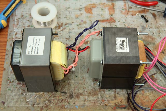
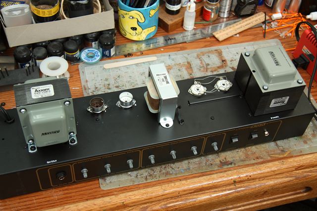
This photo give you an idea of the size of the new transformers compared to the old.You can also see my messy hobby bench here.Lots of paints, brushes and glues frommy miniature soldier painting are visible.
 |
Here's a comparison photos of the old and new output transformers.The new is much bigger and heavier.Luckily the amp case has enough room for the bigger one.Connecting wires are the same number and colors.
 |
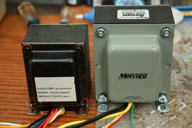
Here is a photo comparing the old and new power transformers.Hopefully the newer one gives clean and wonderful sounding powerto the components.
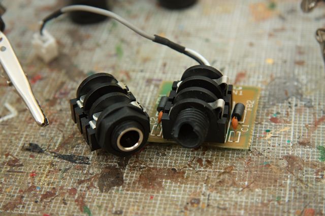 |
This photo shows the new and old guitar input jacks.The older one on the right was loose and wiggly.I wiggled the input jack and the plastic case cracked.The newer jack on the right holds the cable much more tightly.It also has a small metal color, so should not crack as easily.
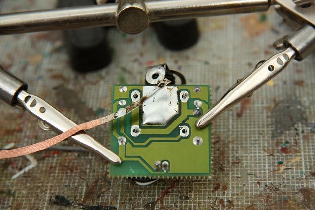 |
This photo shows how to remove the older guitar jack.There is a pretty large circuit pad that connectsthe input jack to the board.It has a lot of solder on it, so you needlots of solder braid to remove the solder.The solder braid is copper wire that sucks up wetsolder, much like a paper towel soaks up liquid.The two alligator clips holding the little boardare known as "helping hands".They free your hands to hold the soldering ironand the wick.
 |
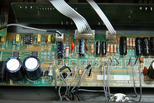
One of the most common mods for a Vox AC15CC is1the bright cap mod.The bright cap is the tiny capacitor next to the leftmost potentiometerin this photo.Most people completely remove it which is saidwill remove excessively bright sounding input.
The original value is 120 pF.Rather than completely remove it, I opted to halve it to 68 pF.In light of all the other mods I've made, and the input treble control,I cannot hear much of a difference this change has made.
 |
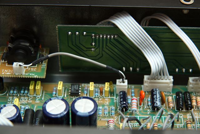
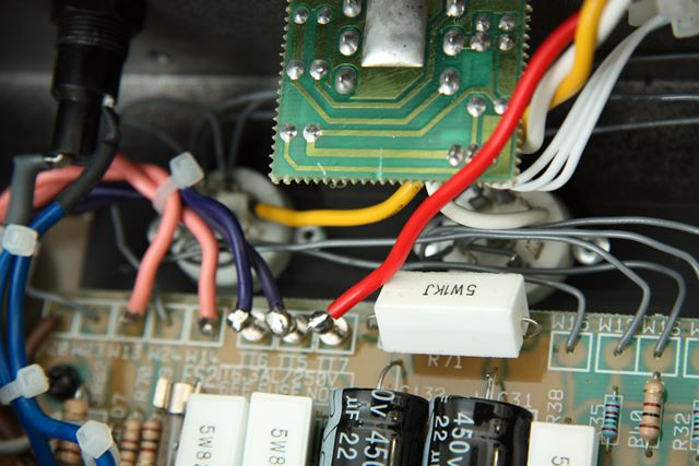
Thisphoto shows the input blocking resistor R71.It is the horizontal white rectangular square resistorat the bottom of the death caps in this photo.This is the resistor that you remove for the choke mod.The new choke leads attach to the board in this place.
In addition to the choke mod, some people also change resistorswhich control the V1 plate voltage to the EL84 power tubes.Deep in the comments section of the Guitar Pug site are theseimportant comments:
I ran my amp for a while without changing any resistors, and the amp ran fine, but I do have NOS 1970's Tesla Hex Plates. I did use JJ's a bit too and they seemed to cope as well. Looking at the schematic, resistors R32/R35 are 1.5k and R39/R40 are 100ohm. These should be changed to 2.2k and 470ohm respectively. I used 1watt carbon film resistors. These valves are suggested by a well known amp tech over on the Vox forums, as they run things a bit 'cooler', but keep the 'correct' sound. Going too high on these values will start to alter the sound of the amp.""In the stock form, the schematic says the power valves should see about 350V on the EL84's, which is already quite high as far as current production valves go. After fitting in the choke, this would go higher, to maybe 370V which is really starting to push the limits.
In keeping with the spirit of this comment, I too swapped out the R32 and R35 resistors from 1.5k to 2.2k and the R39 and R40 resistors from 100 to 470.Just locate them on the board, desolder the older ones, solder in the newer ones.I did not measure the changes, but it sounds logical.
 |
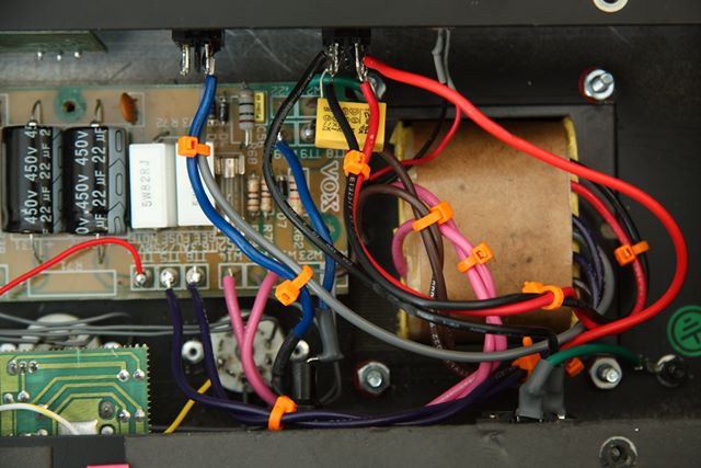
Here's another view of the power supply transformer connections to the board.The brown, pink, and purple wires supply voltages to the tube plates and heaters.Write down all connections or mark them on the schematic.
 |
Here is the older power supply connections to the power switch, standby switch, and on/off light.I've removed the shrink tubing to expose the double pole/double throws switches.Some modders like to replace these plastic switches with heavy metal toggle switches.
 |
This photo shows the replacement power transformer wired in.Notice that I use orange zip ties instead of white or black.That's all they had at the electronic supply store.
I was a little careless with the soldering iron here.Excessive heat on the switches melted the switches somewhat.Luckily they still worked properly.Perhaps one day they will fail in which case I will put in betterswitches and be a little more careful with the soldering iron.
 |
This photo shows the power transformer connectionsto the back of the amplifier.The little switch controls 8 or 16 ohm output impedance.The little circuit board contains the connectorsto the output speaker.Additional red, yellow, and orange wires run to theoutputs of the EL84 power tubes.Disconnect these wires in preparation for replacement.
 |
This shows the new output transformer wired into place.Again I used orange zip ties instead of the white.
Again I was also careless with the soldering iron heat.I nearly melted the impedance select switch.You can also see some black melt on the yellow wire insulation.It was troublesome getting the yellow heavy-duty single wire tostick to the switch.I think it had a coating on it as well.The older wire was multi-stranded and uncoated,and it was much easier to solder.Nevertheless, everything held together and worked.
 |
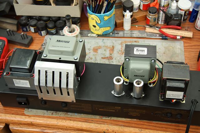
OK, much of the wiring and replacement is done at this point.Here is how the amp head chassis looks after mounting the new components.The choke sits in the middle.
The layout of this amp is somewhat zig-zag.Many well-thought-out amps have a simplelayout that follows the signal pathfrom left-to-right or right-to-left.The power transformer is by the switches, fuses and the electrical supply wires (the mains).The preamp tubes are near the guitar input jack.The output tubes are near the output transformer and the speaker connections.This amplifier goes from guitar jack, all the way to the other side for the preamps,then back to the originating side to the speaker.Kind of circuitorious.
 |
Now that everything is back together and the tubes are in place,I bring up the amp for the first time.That item on the left is a variable AC transformer (or variac),which can take the AC power from zero up to 120 volts.You bring the power up gradually to check for leaks, fires, andexplosions before going full power.
No smoke, and the tube heaters are glowing nicely, so it appearsI have no terrible problems at this point.I pack the amp head back into the combo cabinet.
 |
With the board returned,I plug in a guitar and give it a whirl.No sound.Hmm.I pull on all wires and check all my wiring.Everything seems tight and connected to the right spot.I get out my digital multi-meter and very carefully test voltagesin the hot amp. (Careful! Remember some traces have up to 450 voltsready to zap you.)I notice the power switch continuity seems bad.So I power down and resolder the power switches.
I bring it all up a second time, plug in a guitar. Now I hear the guitar, but it is lost in a sea of noise and hum.I debug all connections again, and I cannot figure out what went wrong.
After a few hours, I decide to call in the real professionals.I bring the amp into Austin Amplifiers.After a few weeks, I get the diagnosis.That plastic tube socket, which obviously caused the previous owner some problems,was faulty.The technician rewired and resoldered the socket, and all was working.
 |
If you have read this far, thanks!I hope to reward you with a few audio clips of how the amp sounds.Mind you, I am just a beginning guitarist, but I hope some scales andsome songs give you an idea of what is possible with this amplifier.It definitely has the sound I like, clean and chimey, with a muchincreased sustain and tone as a result of the mods. I am completely happywith the mods.
There are no pedals or other processing on the input,just an Epiphone Casino guitar straight into the amp.These sounds are recorded with a Shure SM58 beta into an Edirol UA-25EXADC. No post-processing on these clips other than to normalize the volume.
Thanks for visiting the site and reading the article.You must either be interested in guitars and amps, or extremely bored at work.If you like these articles on guitars and music, and you find a site that might be helpfulin explaining how the guitar or music works, please send it to me, and I will share it with all the readers.