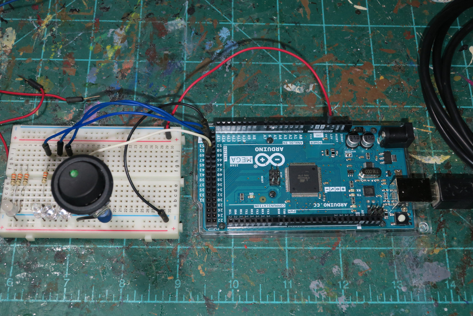
This photo shows my computer prototype to make sure everything works. On the right is the Arduino computer. Arduinos are very small, inexpensive, simple computers. They have CPUs, memory, networking, and popular interfaces such as USB. Arduinos cost from $10 to $30. This version is the Arduino Mega which has lots of digital, analog, and communications pins on the black connectors on the edge. Connectors are expensive, so this is a $30+ version of the Arduino. Here I need a USB connector for providing power and talking to another computer.
The prototyping "bread board" on the left allows you to create circuits quickly and easily without permanent connectors or soldering. Once you figure out what works, you usually move to a more permanent setup.
On the bread board I have four LED lights, and a big round rocker switch. The switch is simply an on/off button like a light switch. It is a latching rocker switch that gives a confirming click when it moves. Press on one side, the switch is on (and the little LED on the button tells you so), and press on the other side, the switch is off (and the LED tells you so). This is also known as a single pole single throw (SPST) switch.
Notice that I have used very few of the connector space around the Arduino. Just four blue wires for lights, and one white wire for the switch. The red and black wires provide power to the bread board, just like a battery plus and minus voltage.
For this project I needed about twelve on/off switches used for flight simulators (parking brakes on/off, landing gear up/down, cabin lights on/off, etc.). The Arduino Mega can handle about 50, but for this first project, I wanted it simple.
I made a paper template for two rows of round switches, six switches in each row. On the far right is a hole for a red/green/blue LED which can be used to signal status such as green for go, yellow for warning, and red for problems.
The template is applied to an ABS plastic project box from Hammond Manufacturing. This box is about 7.5 by 4.5 by 2.5 inches (195 by 115 by 65 mm). I also wanted a black plastic look that would fit in with my other flight simulator gear.
I use a small drill bit to make pilot the holes for the larger 20mm sized switches.
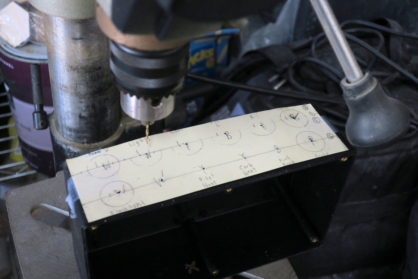
This photo shows drilling holes for the 20mm buttons.
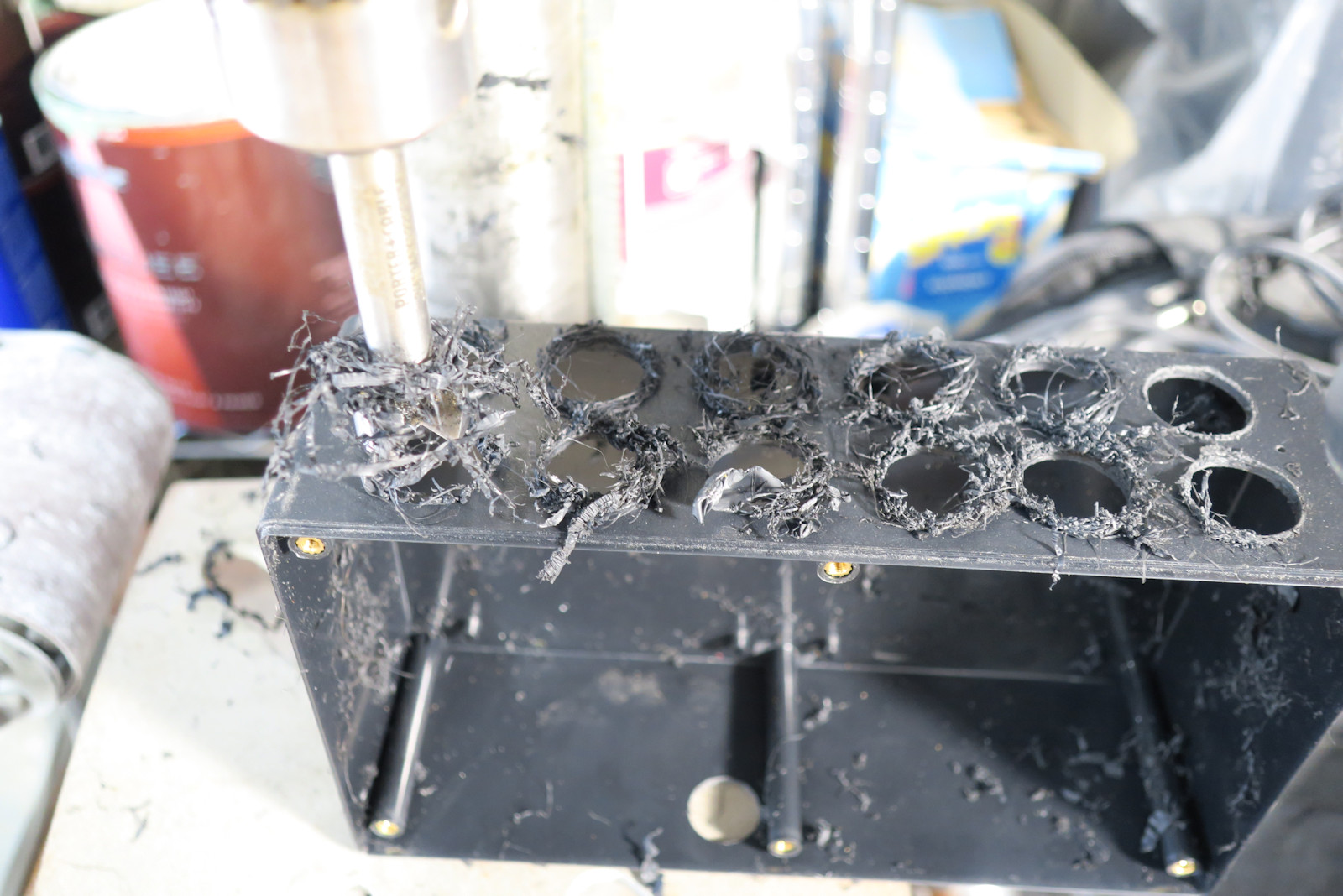
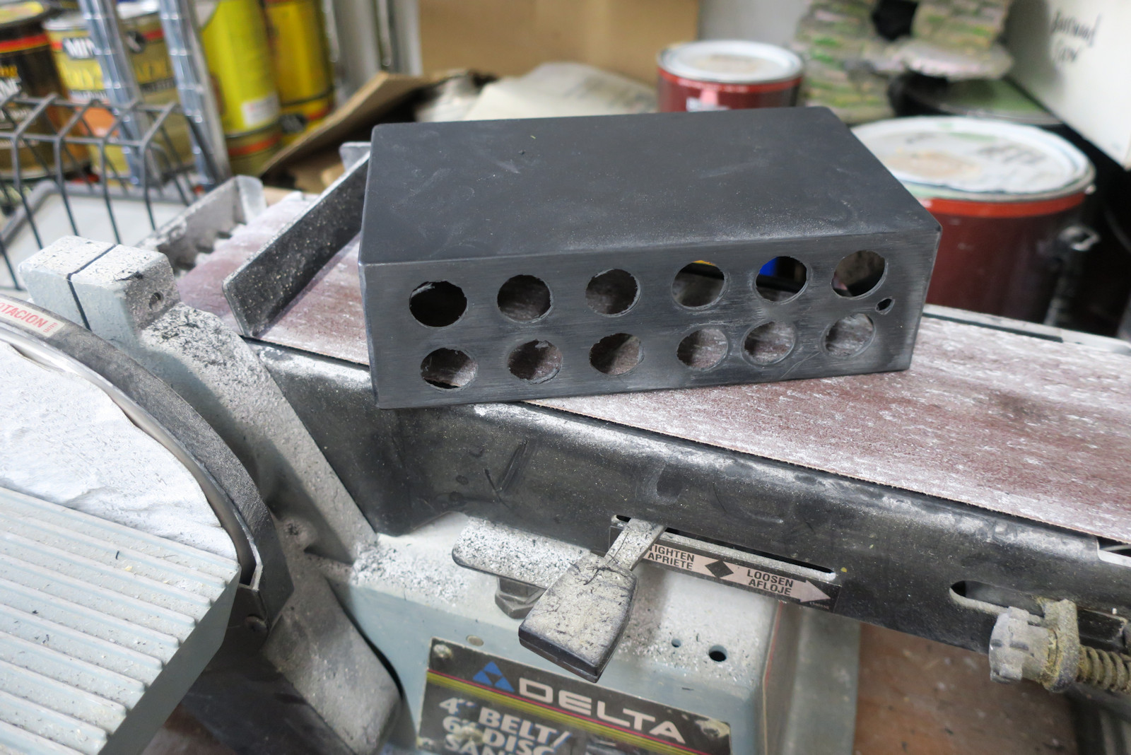
On the left is a Forstner bit making the last hole of the two by six array. Forstners work great on wood, but you can see all sorts of plastic streamers coming out of the ABS plastic holes. I think the bit was moving fast and melting the plastic. Fast or slow, it was tough getting a clean hole in the plastic.
All that plastic cruft on the faceplate came off rather easily with a good belt sander. A few more passes the the front plate will be rather smooth. I will paint it later to get a nice look.
Of course sanding leads to lots of dust and this belt sander has seen hundreds of projects. The white dust is mostly from plaster scenery I make for my miniature wargames..
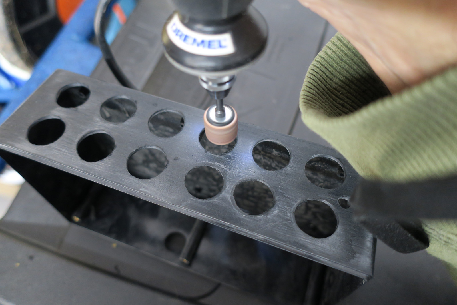
A hand-held Dremel grinder helps make the holes nice and smooth. The holes had to be enlarged slightly to make room for various anti-slip grabbers and locks on the round buttons.
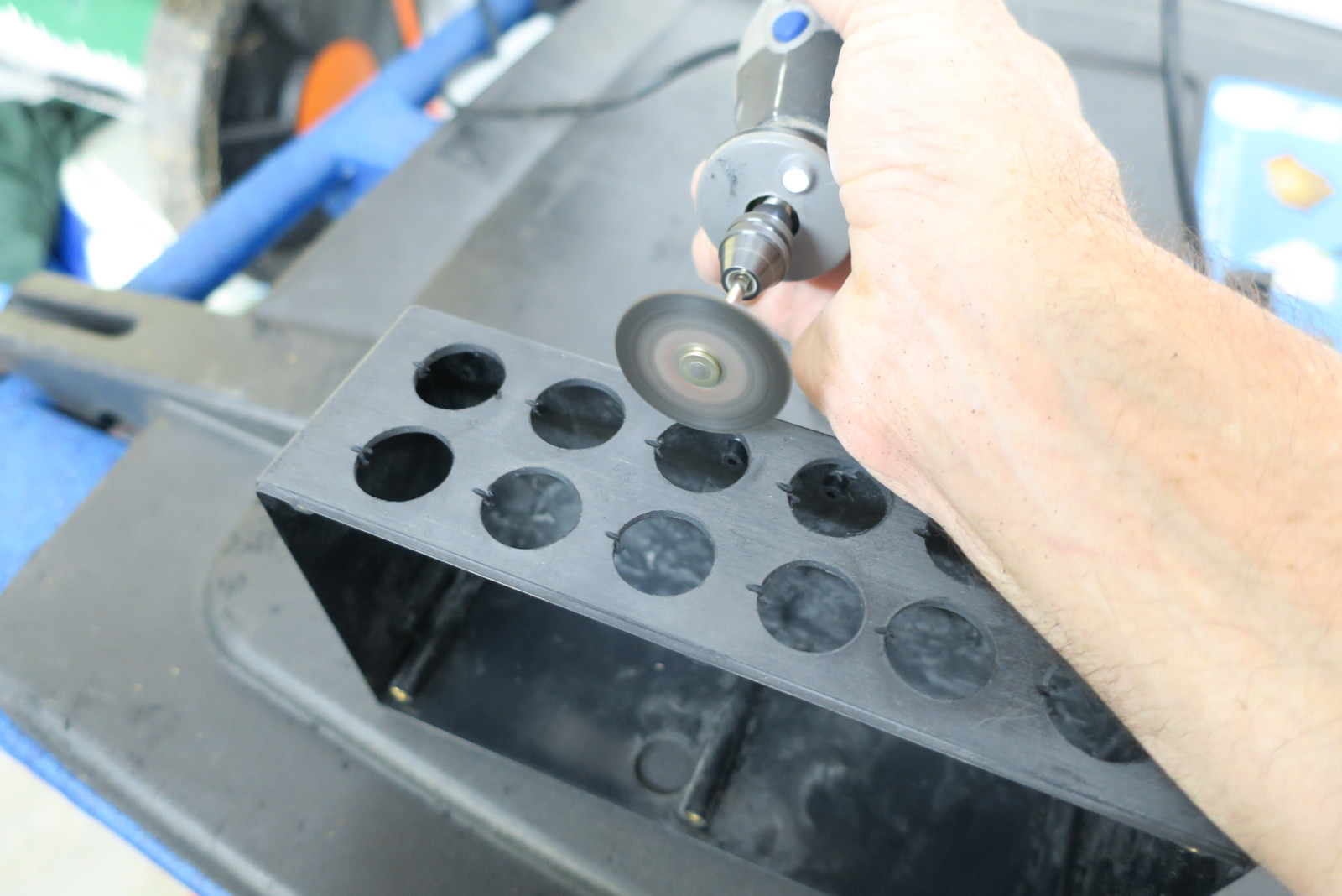
The Dremel tool is also useful for cutting keying slots into the holes for the switches. The key slots accept a protrusion on the button and prevent the buttons from spinning or popping out of the holes.
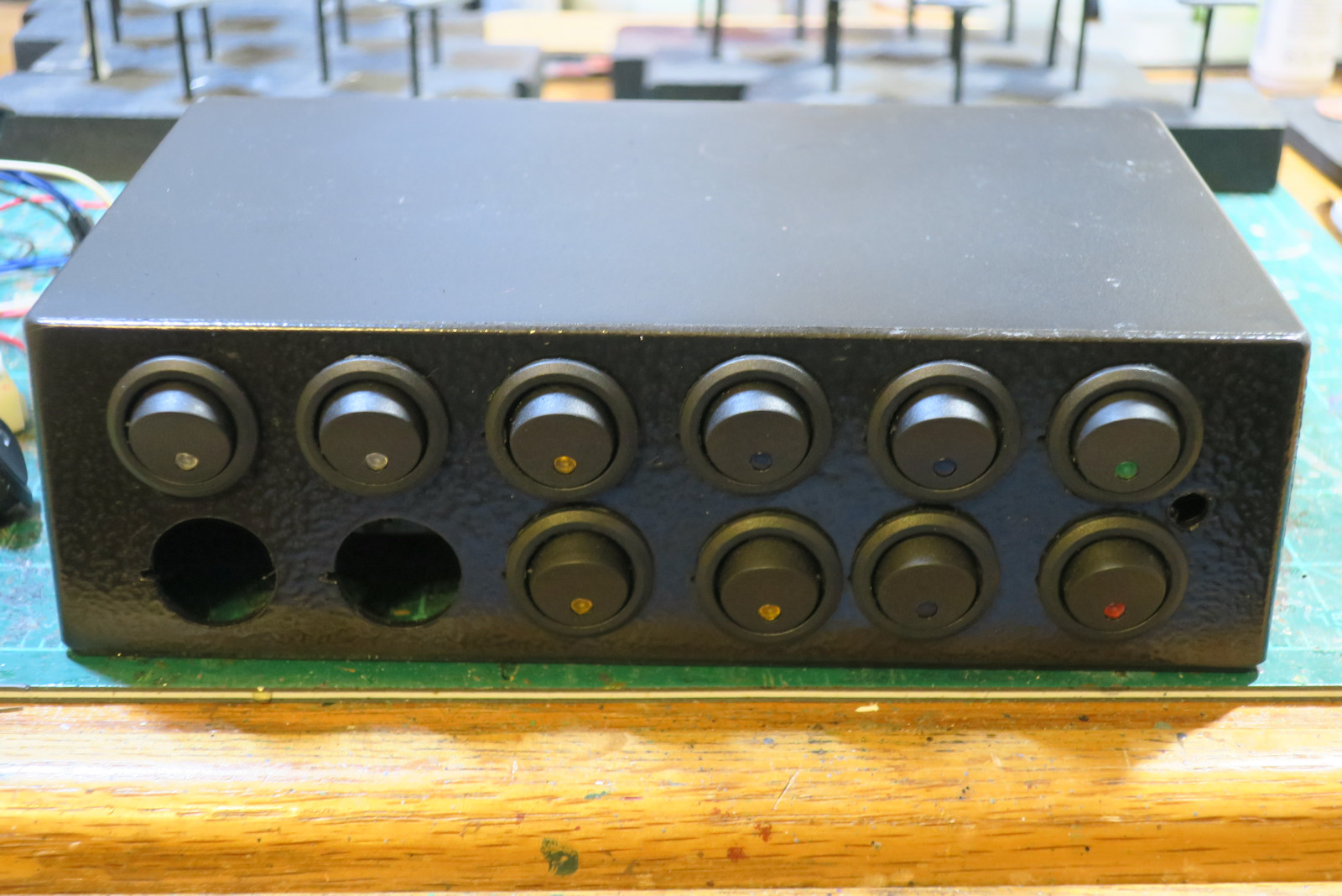
This photo shows most of the buttons installed on the face plate of the project box. The buttons have a pretty tight friction fit and are very unlikely to move on their own. Two more buttons and one RGB LED to go.
The face plate has been painted with Krylon "Hammered Metal" glossy black paint. This makes the plastic project box almost look like a high end stereo.
There is a little bit of a spacing problem with the buttons. One or two fall out of line. Even with a template and pilot holes, I think my attention might have wandered. Oh well, no big problem.
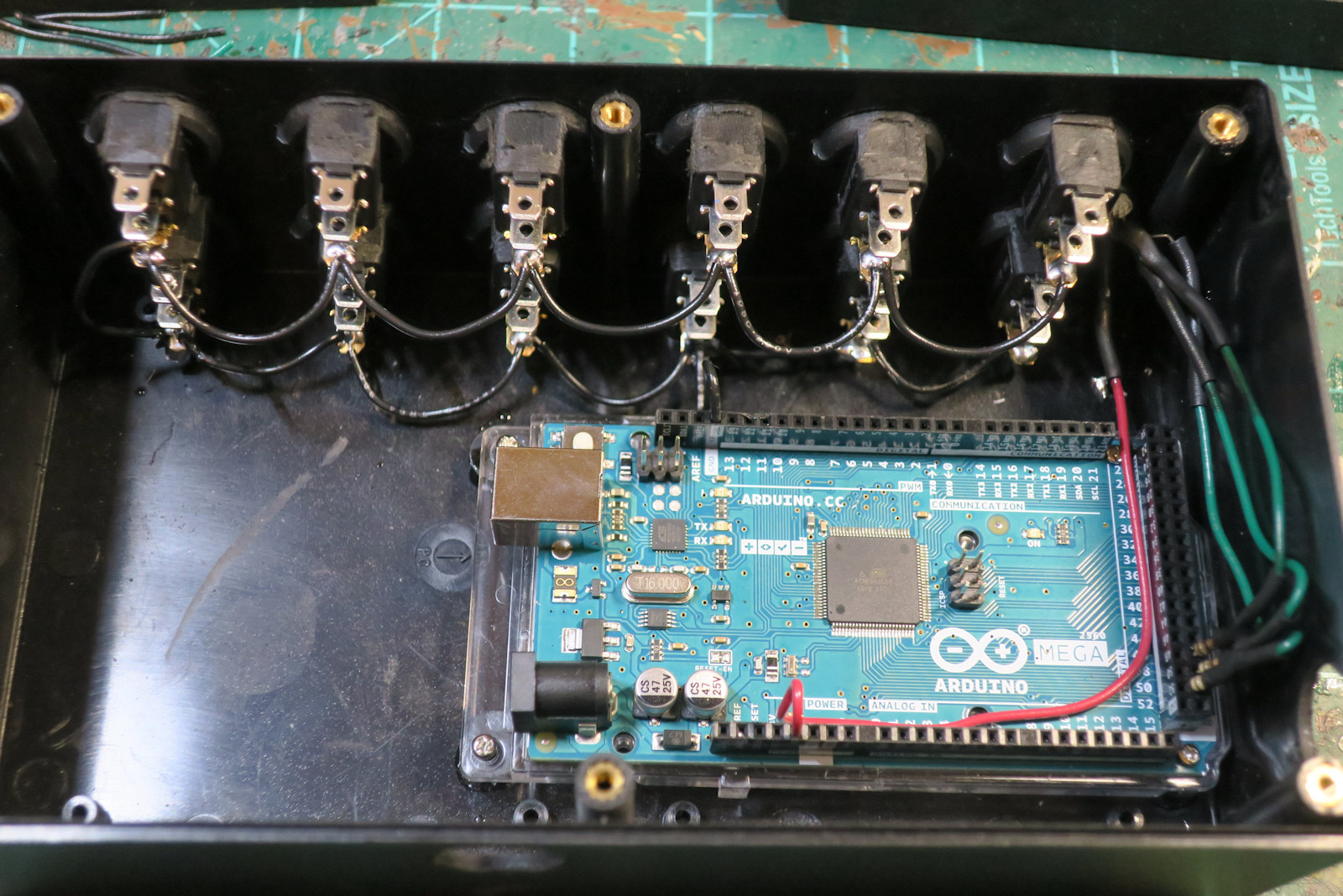
This photo shows the Arduino Mega computer board mounted in the project box. Some boxes have stand offs for mounting boards. This one did not. Instead I epoxied some rubber cylindrical feet to the project box. Then I drilled and screwed the board into the rubber cylinders. That way I can remove the computer if I need to replace it or reuse it.
On the top of the photo you can see the black ground wiring of the switches. Each switch has one side connected to ground, and then a small black lead goes to a ground connector on the Arduino board.
Finally, the status LED wiring is shown on the right side of the photo. The RGB LED is what is known as a common cathode LED. The red wire brings 5 volts to the LED cathode. Then 3 green wires bring each RGB wire back to the Arduino board. I hooked the RGB leads up to digital connectors for a total of 8 color combos. In hind sight, I should have used some of the analog connectors for many more colors and brightnesses. Maybe in a future modification.
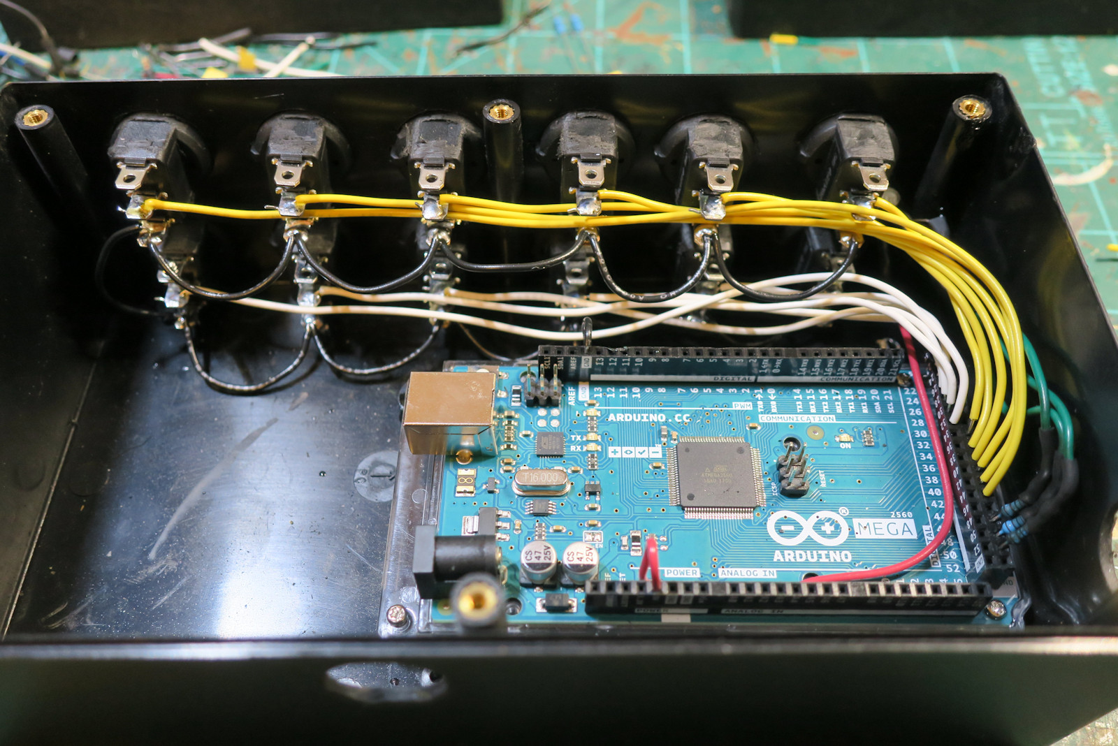
This photo shows twelve yellow and white wires bringing the load connector of the switches back to digital connectors on the Arduino. This is how the Arduino senses the on or off position of the button. The LED light on the button is completely internal to the button and needs no resistor to control the brightness.
You can also see two ports on the project box. One is at the bottom of the photo and one is to the extreme right side. This is for the USB power and communications connection. Originally I was going to route the USB out the back, but I discovered the button box works in a vertical position as well and also saves desk top space. So the USB cable is better going out the side.
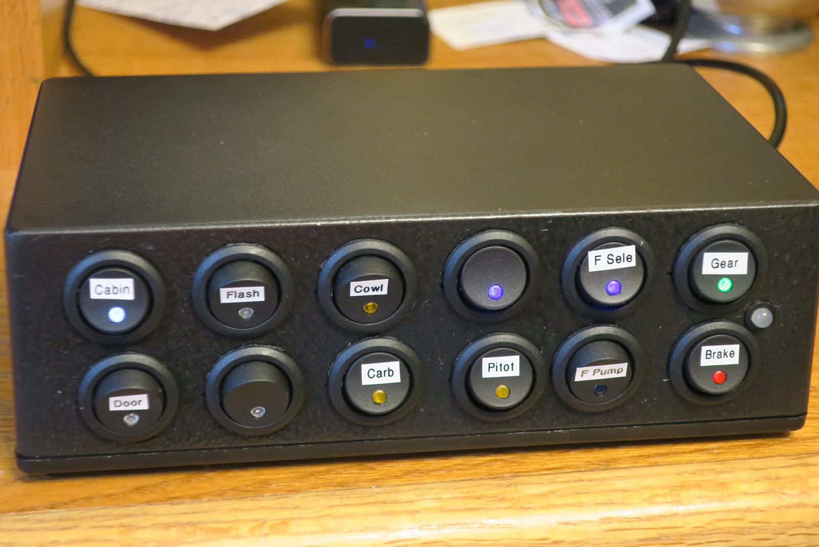
This photo shows a front view of the completed button panel with twelve on/off switches and an RGB status LED. Each button has a tiny label from a label maker, and an LED status light signifying on or off.
The four left buttons have a white LED, and I use these for lighting and electrical switches in the plane. The next three buttons have a yellow LED, and I use this for heat and cowl switches. The next three buttons have a blue LED, and I use this for fuel selectors and pumps. Then there is one green button for landing gear and one red button for the parking brake.
The LED position on this switch is a little odd. Most switches have the LED on the ON side of the rocker. These switches have the LED on the OFF side of the rocker. So with these, you touch the lighted LED to turn it off.
All these switches are easily assignable in software. Right now I have them assigned to functions available in most planes (brakes, fuel, lights, etc.)
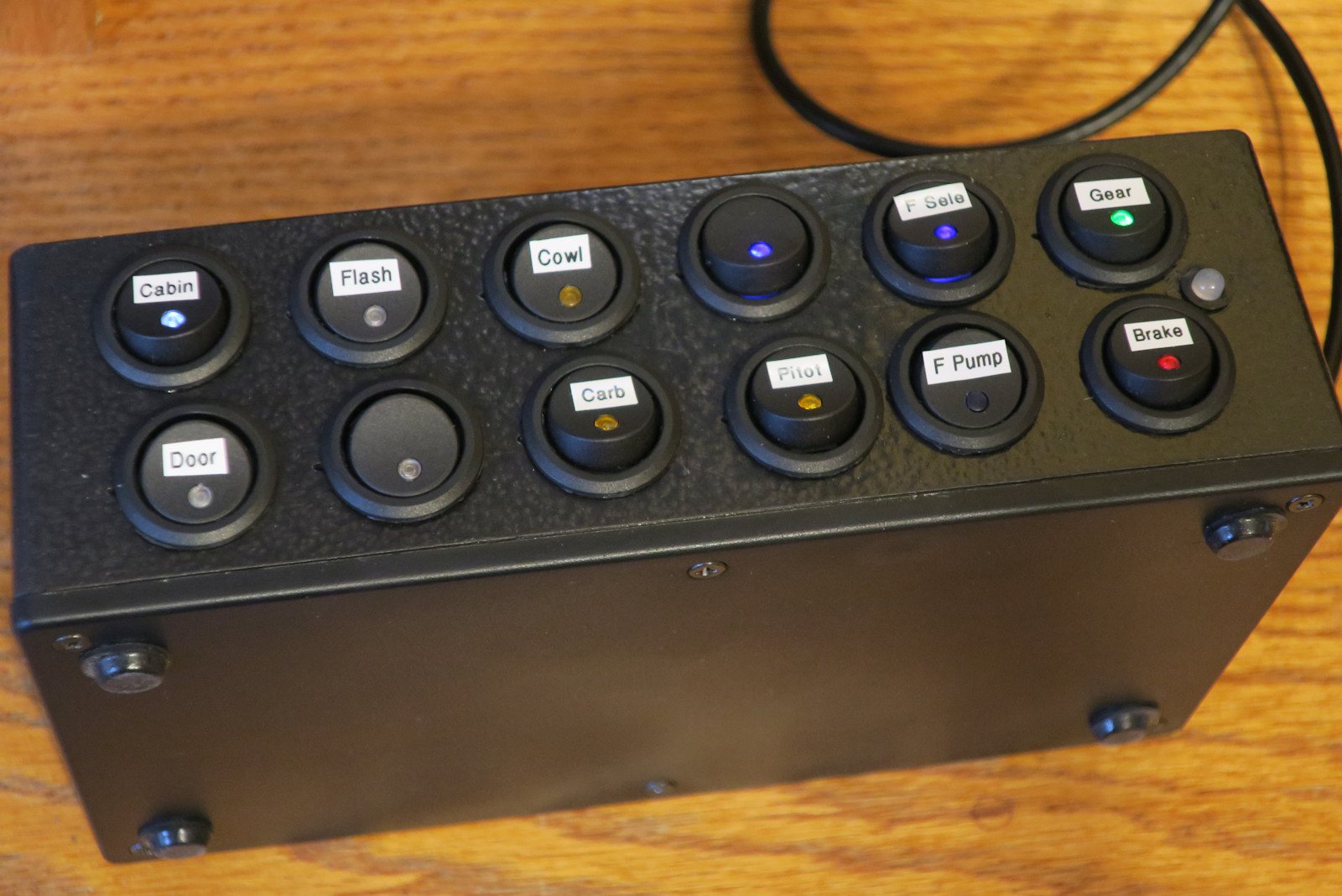
This photo shows the button box in the vertical position. This saves space on the desktop. Notice there are rubber feet on the bottom of the project box. This prevents it from sliding when you press the buttons. However in the vertical position no rubber feet are needed.
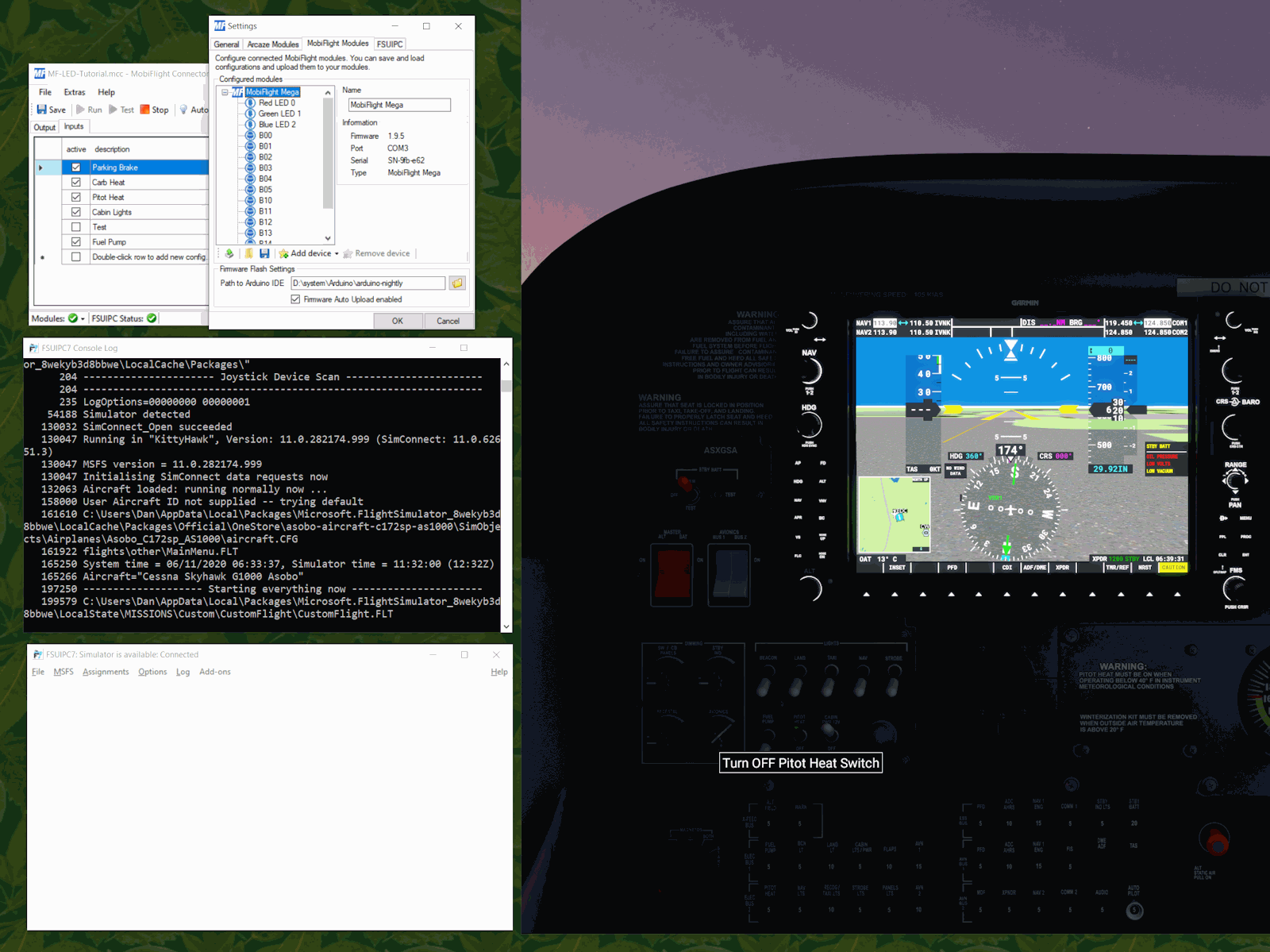
And now the final photo that shows the flight simulator and switches in action. On the right side is the Cessna 172 dashboard in Microsoft Flight Simulator. It still is dark because I have not started the plane. The mouse hovers over the Pitot Heat Switch in the simulator showing the switch label.
On the top left side is the utility MobiFlight. This software speaks to the Arduino board and discovers the status of the board connectors. The Settings window of MobiFlight lets you name the buttons (which I have named B00, B01, etc.) and the three leads to the RGB LED (labeled Red LED 0, Green LED 1, and Blue LED 2). It also other common hardware such as potentiometers, digital encoders, 7 segment displays, and LED panels.
The other window of MobiFlight at the top left shows how you assign the hardware to flight simulator features. I have flight functions such as Parking Brake, Carb Heat assigned to actions in the flight simulator. There are also three important indicators in this window: the run button shows the Arduino software sketch is running, the "Modules" green check mark shows that it is talking to the Arduino board, and the "FSUIPC Status" green check mark is showing that it is talking to the next utility FSUIPC7.
FSUIPC7 stands for Flight Simulator Utility Inter-Process Communications version 7. This is the software which takes a flight simulator command such as "Parking Brake Toggle" from one device/process on the network (MobiFlight) and puts a value in the right place in memory on another device/process on the network (Microsoft Flight Simulator) to understand and act on it. You can see in the console log window on the left that FSUIPC7 finds and connects to your flight simulator software. The other FSUIPC7 window is for saving configurations or performing more complex actions.
In summary, the switches talk to the Arduino, the Arduino talks to MobiFlight, MobiFlight talks to FSUIPC7, and FSUIPC7 talks to the flight simulator. All of this is bidirectional so that what happens on the screen also can be updated on the button box.